
Groove-type compound parabolic concentrating power generation component

A compound parabola and power generation component technology, which is applied in photovoltaic power generation, electrical components, solar thermal power generation, etc., can solve the problems of low effective utilization of solar energy, large light dispersion at the light outlet, and small light concentration angle, etc., to shorten capital recovery The effect of increasing the concentration ratio and large concentration acceptance angle

Active Publication Date: 2015-03-04
INNER MONGOLIA TECHN COLLEGE OF CONSTR +1
View PDF6 Cites 0 Cited by
  • Summary
  • Abstract
  • Description
  • Claims
  • Application Information

AI Technical Summary

Problems solved by technology

[0003] The compound parabolic concentrator appeared in the 1970s. It is composed of multiple parabolic concentrating mirrors. It does not need to track the sun. At most, it only needs to make small adjustments with the seasons. Disadvantages of placing the concentrating angle too small; the traditional trough parabolic concentrator has the problem of large dispersion of light collected by the light outlet due to non-imaging, and in addition, the retroreflection of light in the parabolic concentrator will also cause shadow problems , will lead to low effective utilization of solar energy

Method used


Image

  • Groove-type compound parabolic concentrating power generation component
  • Groove-type compound parabolic concentrating power generation component
  • Groove-type compound parabolic concentrating power generation component

Examples


Embodiment Construction

[0027] The present invention will be described in detail below with reference to the accompanying drawings and examples.

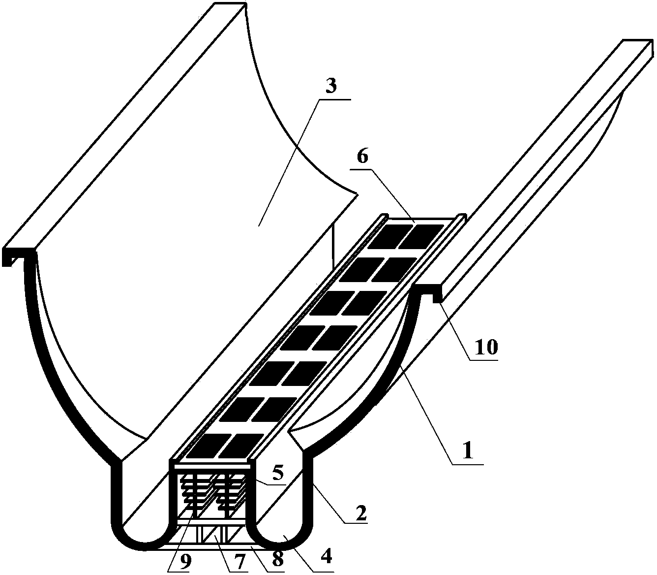
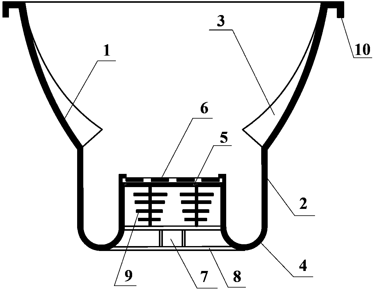
[0028] as attached figure 1 and 2 As shown, the present invention provides a trough-type compound parabolic concentrating power generation assembly, including a left concentrator, a right concentrator, a transparent total reflection film 3, a photovoltaic cell 6, a heat dissipation support plate 5, a fixed bottom plate 8 and heat dissipation ribs Sheet 9; wherein, the left concentrator and the right concentrator are centrosymmetric structures, the horizontal upper half of which is a paraboloid, and the top surface of the paraboloid extends outward horizontally to form a buckle 10 structure, and the horizontal lower half is a groove structure, The trough structure is a structure that extends vertically downward from the parabolic surface. The bottom of the trough structure forms a drainage groove 4. The inner surface of the parabolic surface is a parabolic...


PUM


Abstract

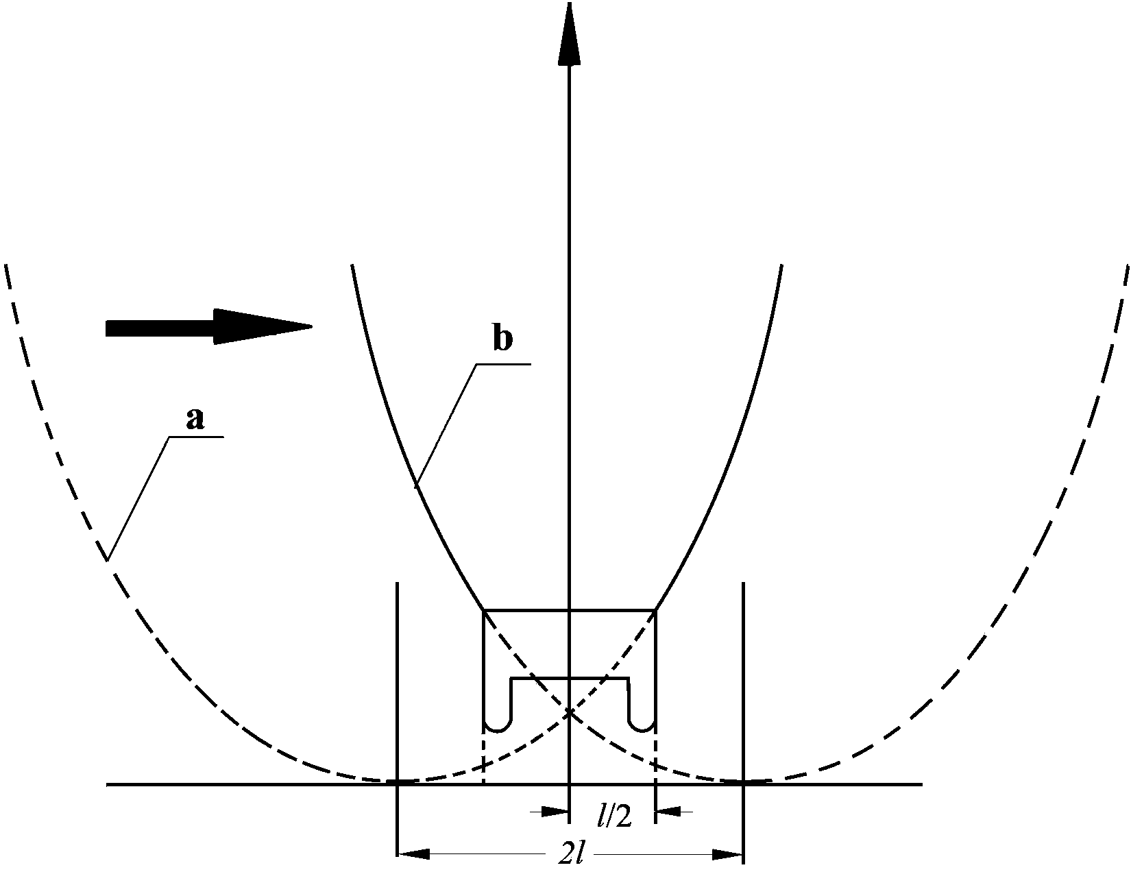
The invention relates to a groove-type compound parabolic concentrating power generation component, and belongs to the field of solar concentrating power generation technology application. The groove-type compound parabolic concentrating power generation component comprises a groove-type compound parabolic reflecting surface, a vertical reflecting surface, a total reflection transparent film, a photovoltaic cell, a heat dissipation support plate, heat dissipation fins, a fixing bottom plate and keel buckles, wherein the groove-type compound parabolic reflecting surface is formed by horizontally moving a compound parabola along a symmetric axis. The parabolic total reflection transparent film with a thin upper portion and a thick lower portion is attached on a parabolic portion, a photovoltaic component is horizontally placed above a focus of a parabolic surface, light can be collected on the photovoltaic component for concentrating power generation when sunlight enters the groove-type compound parabolic reflecting surface, the concentrating angle and the incident drift angle of a concentrator can be enlarged by the total reflection transparent film, the heat dissipation support plate and the heat dissipation fins are mounted at the bottom of the component, hot air generated by the photovoltaic component in power generation is collected to a building energy storage device by the aid of the 'chimney effect' and then is used, the whole device is connected with an inclined slope roof through the fixing bottom plate and the keel buckles, and a semicircular drainage channel has an automatic drainage function.

Description

technical field [0001] The invention relates to a compound parabolic concentrating power generation component, in particular to a compound parabolic concentrating power generation component for building photovoltaic integration, which belongs to the application field of solar concentrating power generation technology. Background technique [0002] At present, building energy consumption is close to 1 / 3 of the total energy consumption of the whole society, and with economic growth, building energy consumption will continue to increase. Accelerating the large-scale application of renewable energy in the building field is one of the effective measures to reduce building energy consumption and adjust the structure of building energy consumption. This application is called building photovoltaic integration. With its unique characteristics, solar photovoltaic power generation technology can provide electricity or heat for multi-energy complementary building energy systems. How to...

Claims


Application Information

Patent Timeline
Patent Type & Authority Patents(China)
IPC IPC(8): H02S40/22H02S40/44H02S40/42
CPCY02E10/52Y02B10/12F24S23/74F24S23/80Y02B10/10Y02B10/20Y02E10/40
Inventor 侯静常泽辉温雯郑宏飞高歌
Owner INNER MONGOLIA TECHN COLLEGE OF CONSTR
Learn More