Cash box with spring balance mechanism

A technology of weighing force and cash drawer, applied in the field of self-service equipment, can solve the problems of small available space of cash drawer, waste of pallet space, and time-consuming, etc., and achieve the effect of improving space utilization rate, saving time, and being convenient to use.

Inactive Publication Date: 2015-08-26
EASYWAY SUZHOU ELECTRONICS TECH
View PDF5 Cites 0 Cited by
  • Summary
  • Abstract
  • Description
  • Claims
  • Application Information

AI Technical Summary

Problems solved by technology

[0003] The cash box used to store banknotes is provided with a slidable supporting plate, and the lower end of the supporting plate is connected with a spring. The banknotes are pushed from the entrance of the front end of the cash box into the cash box by the driving force. When the banknotes are stacked more and more For a long time, it is easy to have the following defects: 1. Since the spring is compressed shorter and shorter, the upward elastic force generated by the spring on the supporting plate is getting bigger and bigger, so the driving force used to push the banknote needs to be bigger and bigger to resist The elastic force of the spring pushes the banknotes into the cash box; 2. When the spring is compressed to the shortest, the supporting plate is resisted by the spring at a certain position and can no longer move, and the space behind the supporting plate is wasted, making it used for storing banknotes The available space of the cash box is relatively small, wasting a lot of space resources, resulting in frequent and time-consuming removal of banknotes for new banknotes to enter the cash box

Method used


Image

  • Cash box with spring balance mechanism
  • Cash box with spring balance mechanism
  • Cash box with spring balance mechanism

Examples


Embodiment Construction

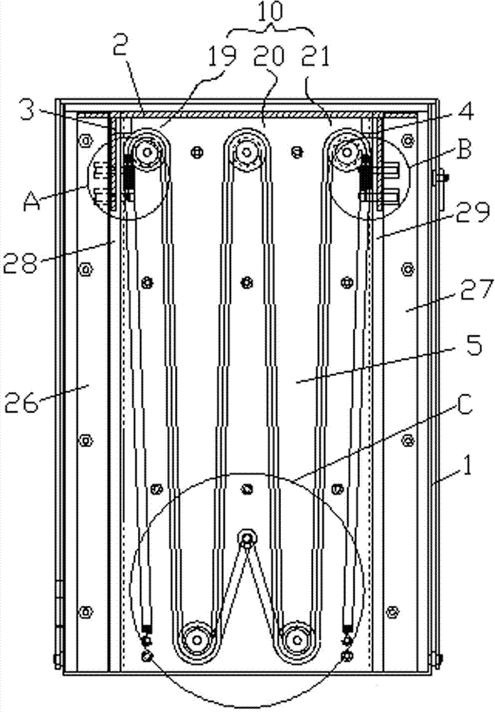
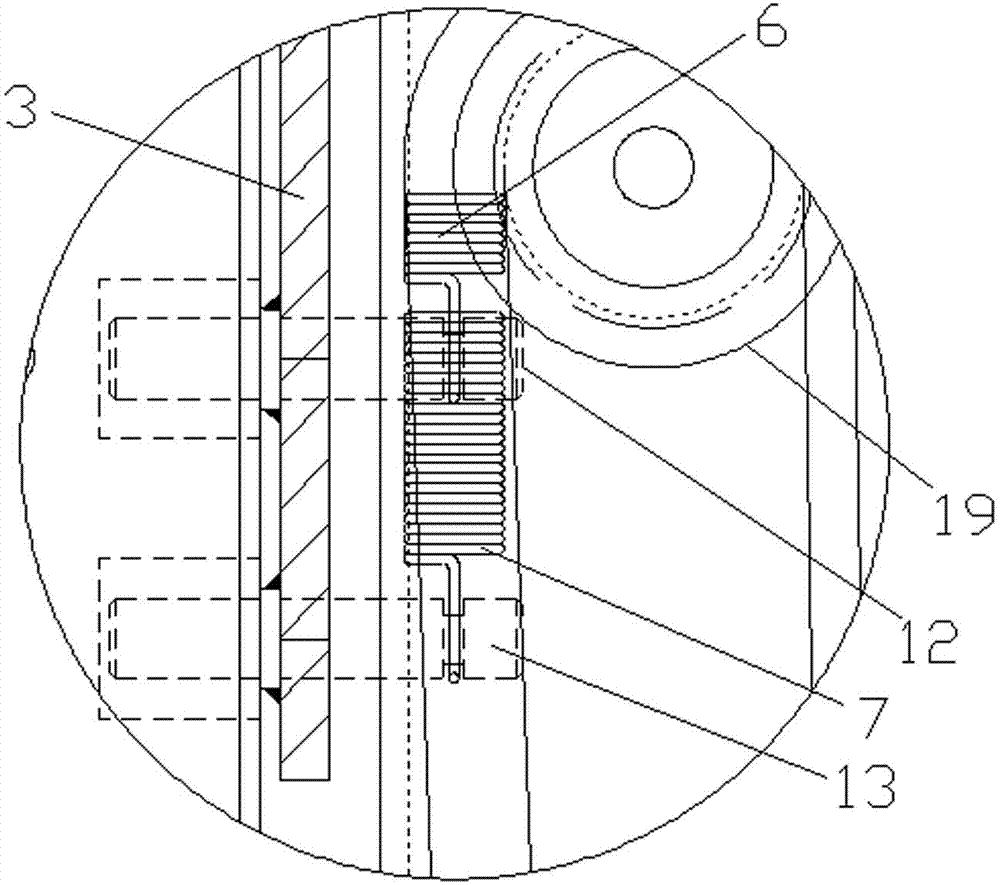
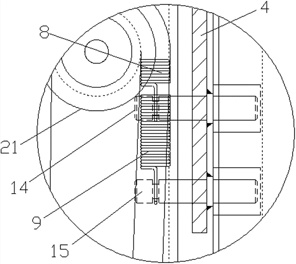
[0022] The present invention will now be further described in detail in conjunction with the accompanying drawings and embodiments. These drawings are all simplified schematic diagrams, only illustrating the basic structure of the present invention in a schematic manner, so it only shows the composition related to the present invention.

[0023] Such as Figure 1-Figure 8 As shown, a spring balance mechanism for a cash box includes a box body 1 and a supporting plate 2 located in the box body 1, and the two ends of the supporting plate 2 are respectively vertically connected with a first slide plate 3 and a second slide plate 4, The supporting plate 5 vertically arranged with the supporting plate 2 and the first spring 6, the second spring 7, the third spring 8, and the fourth spring 9 are installed in the described box body 1, and the upper and lower ends of the supporting plate 5 are respectively A first guide wheel set 10 and a second guide wheel set 11 are provided, and on...


PUM


Abstract

The invention relates to a spring force-balance mechanism for a cashbox. The spring force-balance mechanism comprises a box body and a carrying plate located in the box body, wherein two ends of the carrying plate are respectively and vertically connected with a first slide plate and a second slide plate; a supporting plate which is vertically arranged with the carrying plate, a first spring, a second spring, a third spring and a fourth spring are installed in the box body; a first guide wheel group and a second guide wheel group are respectively arranged at the upper end and the lower end of the supporting plate; one ends of the first spring and the second spring are connected to the first slide plate; one ends of the third spring and the fourth spring are connected to the second slide plate; the other ends of the first spring and the third spring are connected with the supporting plate after passing through parts of the first guide wheel group and the second guide wheel group; and the other ends of the second spring and the fourth spring are connected with the supporting plate after passing through the first guide wheel group and the second guide wheel group. The spring force-balance mechanism for the cashbox, disclosed by the invention, is simple in structure, capable of fully filling cash in the box body, large in space utilization rate, and constant in pushing force for pushing the cash.

Description

technical field [0001] The invention relates to a self-service device, in particular to a spring balance mechanism for a cash box. Background technique [0002] With the continuous development of science and technology, people's living standards are also developing rapidly. Therefore, many self-service devices have emerged as the times require. With the emergence of self-service equipment such as automatic vending machines and automatic ticket vending machines, banknotes are also more and more widely used on these equipment. With the wide application of banknotes in self-service equipment, the requirements for the reliability and maintainability of banknote processing devices in the self-service system are getting higher and higher. [0003] The cash box used to store banknotes is provided with a slidable supporting plate, and the lower end of the supporting plate is connected with a spring. The banknotes are pushed from the entrance of the front end of the cash box int...

Claims


Application Information

Patent Timeline
Patent Type & Authority Patents(China)
IPC IPC(8): G07G1/10
Inventor 杨云贵毕虎杰容易温祖茂
Owner EASYWAY SUZHOU ELECTRONICS TECH
Why Eureka
Try Eureka