
Flow field characteristic experiment device of combustion chamber of hydrogen-burning gas turbine

A technology of gas turbines and experimental devices, which is applied in the direction of measuring devices, aerodynamic tests, and machine/structural component tests, etc. It can solve the problems of inability to obtain test results, long research cycle, poor followability, etc., and achieve convenient recording and processing , Debugging is flexible and convenient, and the effect of reducing debugging time

Inactive Publication Date: 2015-02-25
DALIAN MARITIME UNIVERSITY
View PDF4 Cites 2 Cited by
  • Summary
  • Abstract
  • Description
  • Claims
  • Application Information

AI Technical Summary

Problems solved by technology

[0004] Develop and develop gas turbine combustors that use hydrogen-rich syngas and pure hydrogen gas, and conduct experimental research on new concept combustors under operating conditions. The research period is long, the risk is high, and the cost is huge.
Conventional gas turbine combustor flow characteristics experimental research, using five-hole probe or seven-hole probe to measure the velocity field, the spatial coordinate position of the measuring point is not determined accurately, if the structure of the combustion chamber is complex, the probe will seriously damage the velocity of the measuring point distribution, not only cannot accurately reflect the real velocity distribution of the combustion chamber, but also the experimental data recording and processing are cumbersome
Although the Particle Image Velocimetry (PIV) test method is currently used to conduct experimental research on the flow characteristics of the combustion chamber, the uneven distribution of the test area and poor followability of the tracer particles will directly affect the measurement results during the experiment.
Especially for different test conditions, the current PIV test system debugging is not only time-consuming, but also cannot obtain ideal test results under some working conditions

Method used


Image

  • Flow field characteristic experiment device of combustion chamber of hydrogen-burning gas turbine
  • Flow field characteristic experiment device of combustion chamber of hydrogen-burning gas turbine
  • Flow field characteristic experiment device of combustion chamber of hydrogen-burning gas turbine

Examples


Embodiment Construction

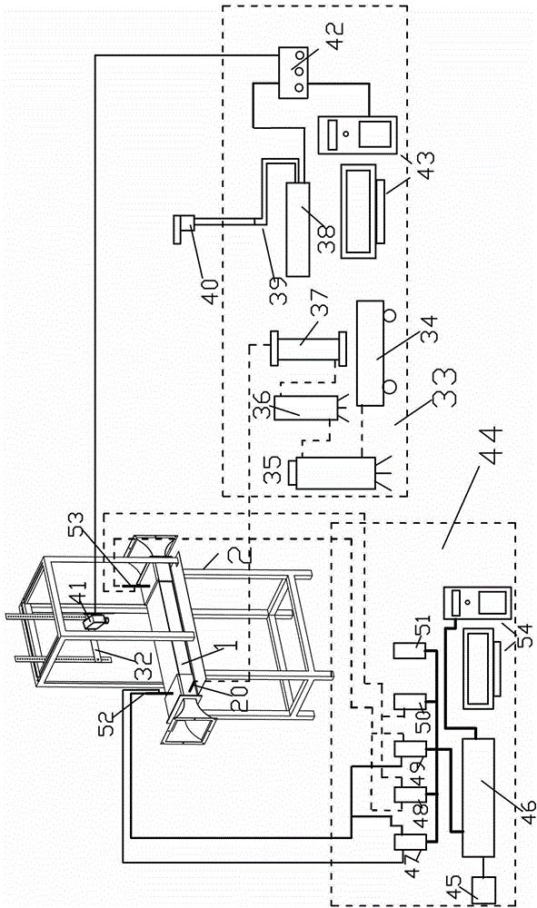
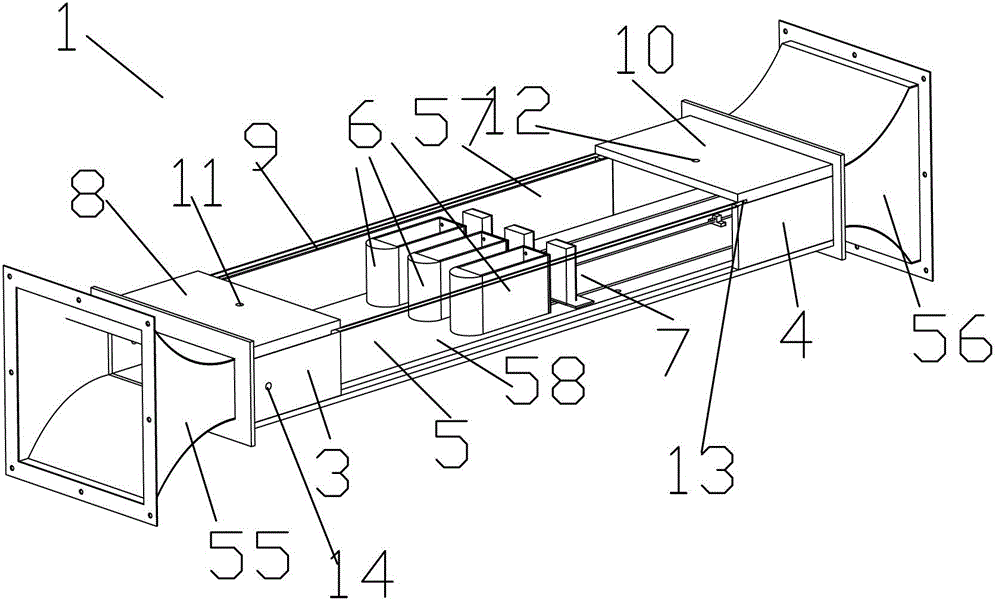
[0038] The present invention will be further described below in conjunction with the accompanying drawings and specific embodiments. Such as Figure 1-10 As shown, an experimental device for flow field characteristics of a hydrogen-fired gas turbine combustor, including three pairs of blunt bodies arranged in a combustor test piece 1, a PIV test bench 2, a PIV test system 33, and a differential pressure and ambient temperature test system 44;

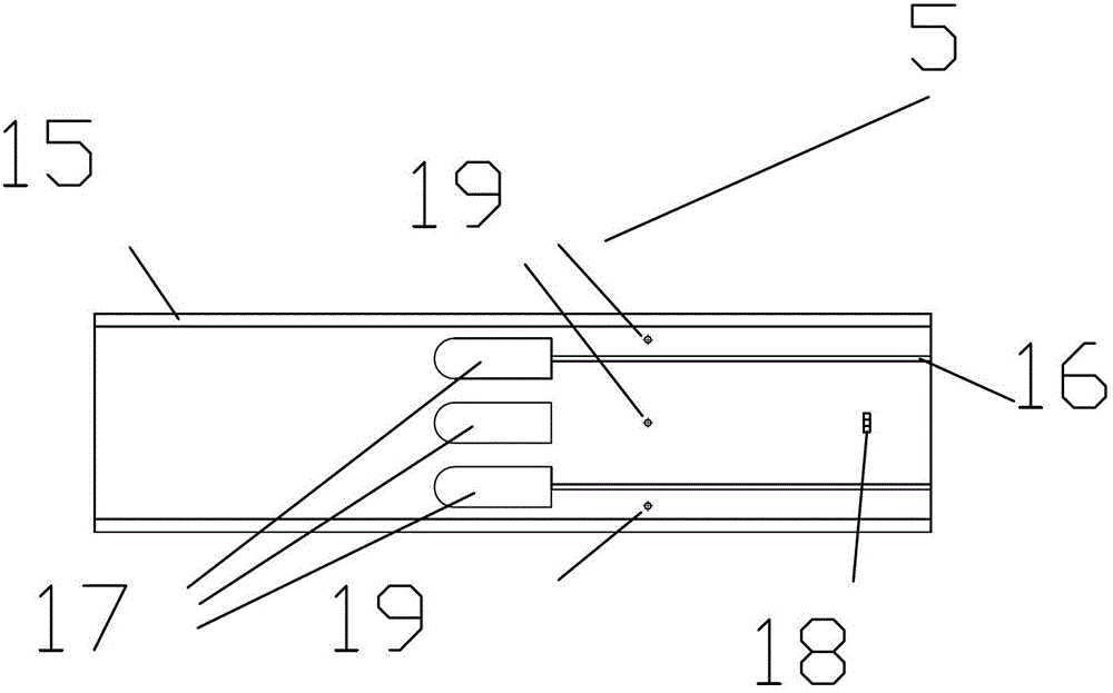
[0039] The three pairs of blunt body arrangement combustion chamber test piece 1 includes a front side plate 3, a rear side plate 4, a bottom plate 5, a front blunt body 6, a rear blunt body and its auxiliary mechanism 7, a front top plate 8, matte glass, Top glass plate 57, side glass plate 58, rear top plate 10, air intake flange 55 and exhaust flange 56; the bottom plate 5 is provided with bottom plate glass slot 15, rear blunt body moving channel 16, front Blunt body sockets 17 and air holes 19, and screw supports 18 are arranged; ...


PUM


Abstract

The invention discloses a flow field characteristic experiment device of a combustion chamber of a hydrogen-burning gas turbine. The flow field characteristic experiment device comprises three pairs of bluff body arrangement combustion chamber experiment pieces, a particle image velocimetry (PIV) test platform frame, a PIV test system and a pressure difference and environment temperature test system. The three pairs of bluff body arrangement combustion chamber experiment pieces comprise a front lateral plate, a front bluff body, a back bluff body, an affiliation mechanism of the back bluff body, a front top plate and a back top plate. A tracer particle injection pipe jack is arranged on the front lateral plate, an inlet speed probe jack is arranged on the front top plate, and an outlet speed probe jack is arranged on the back top plate. A tracer particle generator is connected with the tracer particle injection pipe jack on the front lateral plate. The device adopts the PIV test technology, selects reasonable combustion chamber position, reasonably mingles tracer particles into a main gas flow under the effects of the tracer particle generator and a tracer particle injection pipe, enables tracking particles in the test area to be evenly distributed and conducts visualization experiment of cold state flowing speed vector distribution of three pairs of bluff arrangement combustion chambers.

Description

technical field [0001] The invention relates to a hydrogen-burning gas turbine experimental device, in particular to a hydrogen-burning gas turbine combustor flow field characteristic experimental device. Background technique [0002] The development, promotion and application of Integrated Gasification Combined Cycle (IGCC) technology can realize the sustainable development of coal-fired power generation with near zero emissions. At present, developed countries such as the United States, Germany, the United Kingdom, and Japan have invested heavily in R&D and demonstration of IGCC technology. The process systems and key technologies involved in IGCC technology have become hot spots in the research and development of the international energy field. Carry out comprehensive and in-depth research on the structure and performance of gas turbine combustors burning hydrogen-rich syngas and pure hydrogen gas and their matching with modern gas turbines, and make technical reserves an...

Claims


Application Information

Patent Timeline
Patent Type & Authority Patents(China)
IPC IPC(8): G01M9/00
Inventor 邓洋波王玉龙徐震孙海涛
Owner DALIAN MARITIME UNIVERSITY
Learn More