
Dispatching winch

A winch and shunting technology, which is applied to railway car body components, railway vehicle traction devices, hoisting devices, etc., can solve the problems of large space occupation, complex layout of shunting winch system, and low service life

Active Publication Date: 2013-04-03
TRIUMPH HEAVY IND
View PDF11 Cites 4 Cited by
  • Summary
  • Abstract
  • Description
  • Claims
  • Application Information

AI Technical Summary

Problems solved by technology

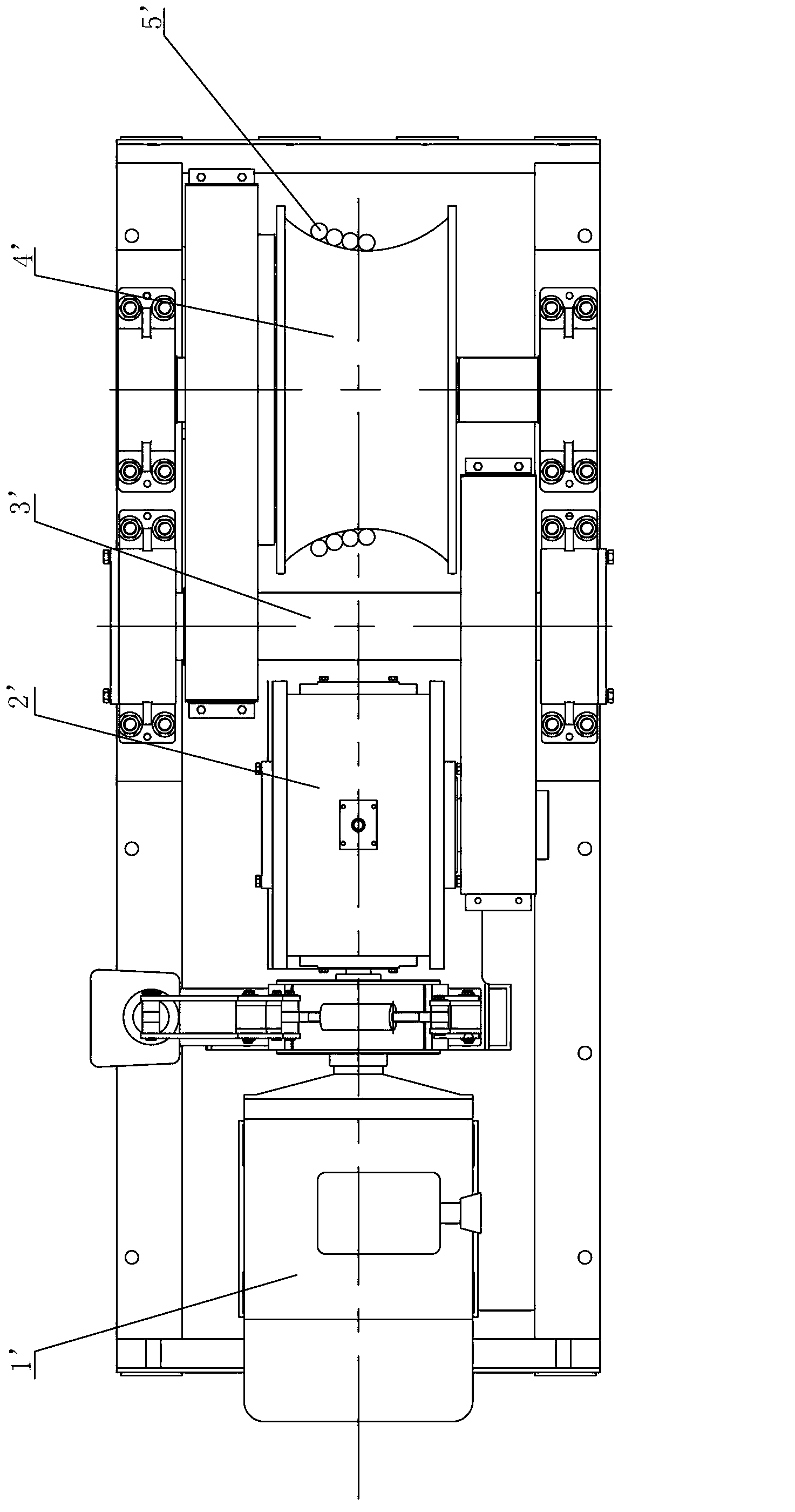
[0003] The layout of the shunting winch system with this structure is relatively complicated, because the steel wire rope is a closed endless rope, when the friction force between it and the drum provides traction, it must be ensured that the steel wire rope is always in a tensioned state, thus requiring Various devices such as tensioning device, tail wheel device, guide wheel, rope pulley, rope support wheel, and traction iron ox are installed, which occupy a large space and have many fault points, and the steel wire rope is always on each tail wheel, rope pulley, The friction on the rope support wheel and the drum causes serious damage and low life. Because it is a closed cycle, its service length is more than twice the transport distance, and the waste is also very serious. slipping, resulting in insufficient pulling force

Method used


Image

  • Dispatching winch
  • Dispatching winch
  • Dispatching winch

Examples


Embodiment Construction

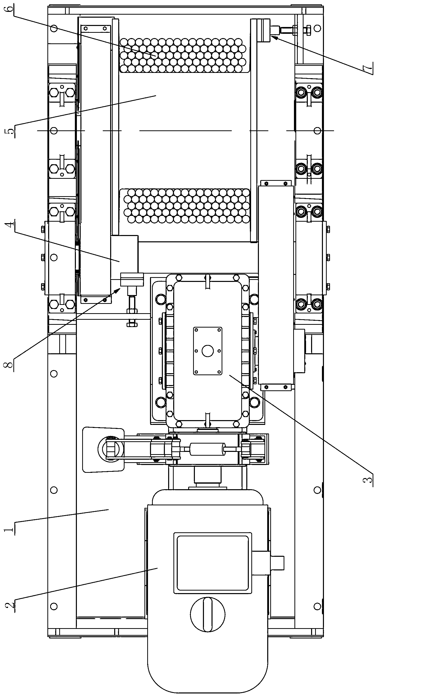
[0016] like figure 2 As shown, the shunting winch of the present invention includes a base 1, a steel wire rope 6 and a motor 2 supported on the base 1, a speed reducer 3, a secondary shaft 4, and a reel 5. The motor 2 drives the speed reducer 3 through a coupling, and the speed reducer 3 The output end of the output end is connected to the auxiliary shaft 4 to drive it to rotate, and the auxiliary shaft 4 is connected to the reel 5 to drive it to rotate. One end of the wire rope 6 is fixed on the reel 5, and the rotation of the reel 5 can drive the wire rope 6 to be wound on or from the reel. Detachment, the other end of the wire rope 6 or somewhere in the middle is connected to the train. Specifically, it is connected to the train through a hook to facilitate separation. Meters, make the wire rope 6 regularly wound on the reel 5.

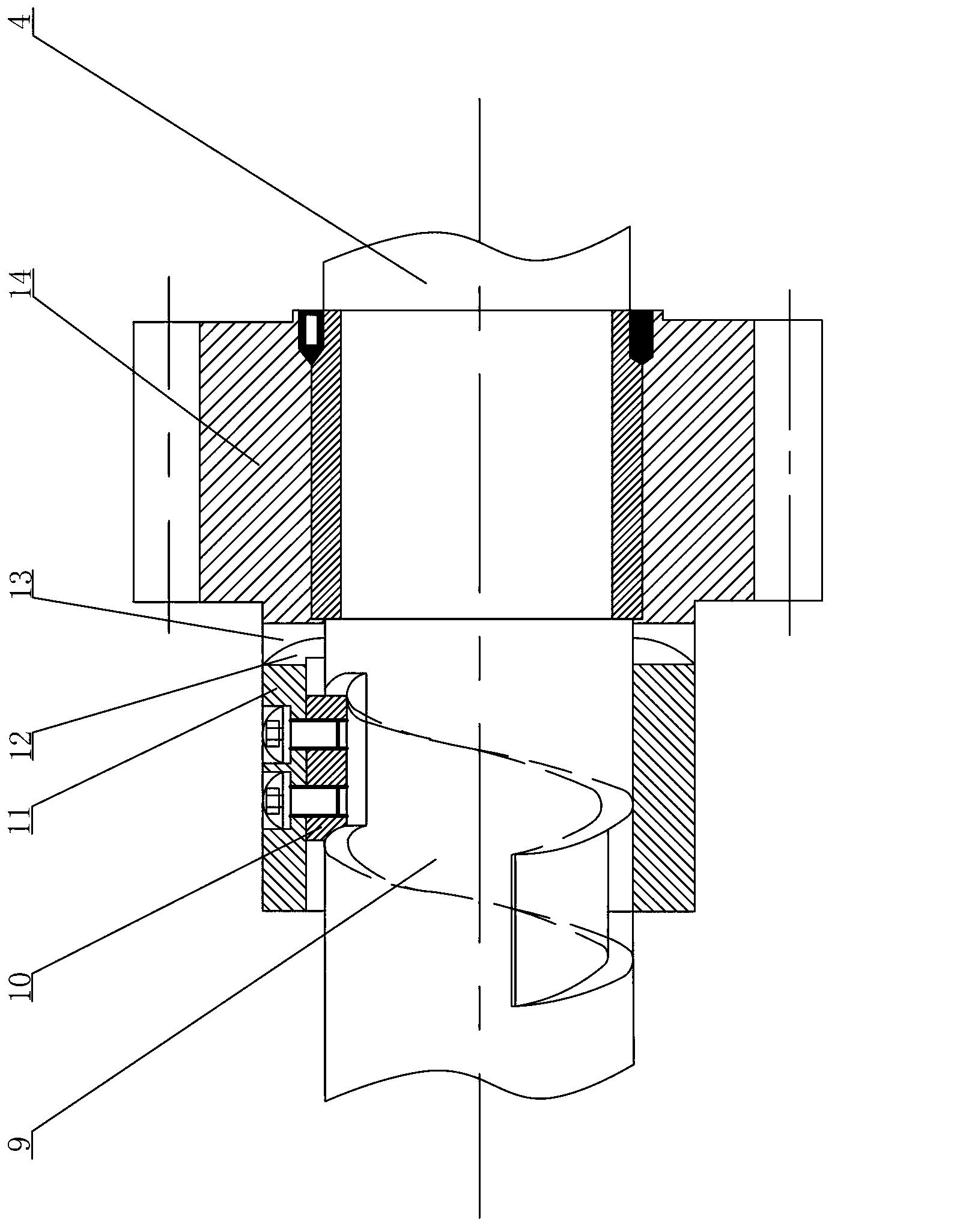
[0017] An automatic clutch device 8 is installed on the auxiliary shaft 4, and the specific structure is as follows: image 3 As shown, there ...


PUM


Abstract

The invention relates to a winch which is used for dispatching a trail train to load and unload goods in transporting places. The invention aims to provide the dispatching winch with a novel structure. The dispatching winch is simple in structure, and a series of auxiliary equipment, such as a tension device, is not required, so that the cost of the equipment is reduced. The dispatching winch comprises a pedestal, a steel wire rope, a motor, a speed reducer, an auxiliary shaft and a reel, wherein the motor is supported on the pedestal and is connected with the speed reducer through a coupler; an output end of the speed reducer is connected with the auxiliary shaft; the auxiliary shaft is connected with the reel; one end of the steel wire rope is fixedly arranged on the reel; the reel rotates to drive the steel wire rope to be wound on the reel or separated from the reel; an automatic clutch device is arranged on the auxiliary shaft; and the auxiliary shaft outputs power to the reel through the automatic clutch device.

Description

technical field [0001] The invention relates to a winch structure used for dispatching trains in coal mines, coal washing plants, power plants, cement plants, ports and other railway trains when loading and unloading goods in transportation places. Background technique [0002] The shunting structure in the prior art is the endless rope type, that is, the winch drives a closed wire rope without a pole to circulate, and the wire rope is connected to the train to pull it to slide along the track. The specific structure of the winch is as follows: figure 1 As shown, the motor 1' drives the reducer 2' through the coupling. For safety reasons, an electro-hydraulic controller is installed on the coupling. The output end of the reducer 2' is connected to the auxiliary shaft 3'. The gear meshing of the motor 1' transmits the power of the motor 1' to the sub-shaft, and the sub-shaft 3' drives the reel 4' to rotate through the gear meshing with the gear of the reel 4', and the endles...

Claims


Application Information

Patent Timeline
Patent Type & Authority Applications(China)
IPC IPC(8): B66D1/60B66D1/14B66D1/36B61J3/04
Inventor 陶永芹彭树权陈志强张钦黄涛
Owner TRIUMPH HEAVY IND
Learn More