Tray separation device

A pallet separation and unification technology, used in transportation and packaging, destacking of objects, etc., can solve problems such as large vibration, instability, and lowering, and achieve the effect of stable separation operation, high separation efficiency, and reduction of hard friction problems.

Active Publication Date: 2015-06-17
深圳市土世界环保科技工程有限公司
View PDF5 Cites 0 Cited by
  • Summary
  • Abstract
  • Description
  • Claims
  • Application Information

AI Technical Summary

Problems solved by technology

[0002] The block forming process includes a series of steps, involving the operation of pallets and bricks, including the separation of bricks and pallets, the stacking of bricks and pallets, and the separation of stacked bricks and pallets. The pallet separation method is generally In order to pull out or push out the bottom tray one by one, the current tray separation device is generally a simple push-out mechanism, which directly pulls out or pushes out the bottom tray by force. There is a lot of friction, and the unseparated pallet located on the bottom pallet is also in an unstable state during the whole process, which will cause damage to the pallet and reduce the service life. The pallet falls directly on the support platform, causing large vibrations, and the separation action is unreliable and unstable

Method used


Image

  • Tray separation device
  • Tray separation device
  • Tray separation device

Examples


Embodiment Construction

[0040] In order to further explain the technical solution of the present invention, the present invention will be described in detail below through specific examples.

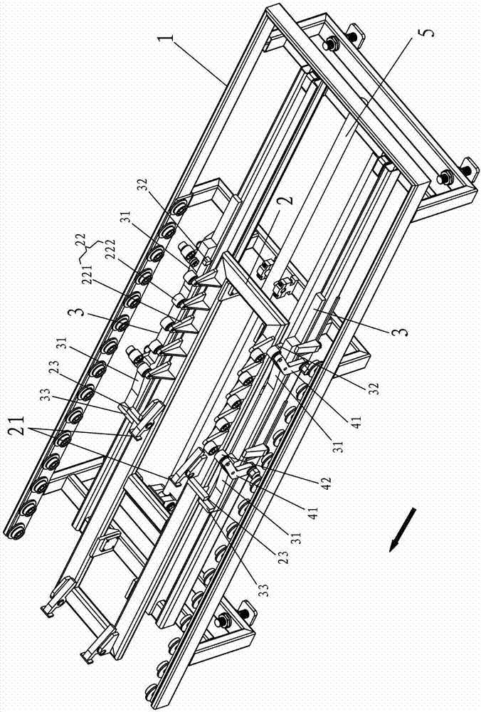
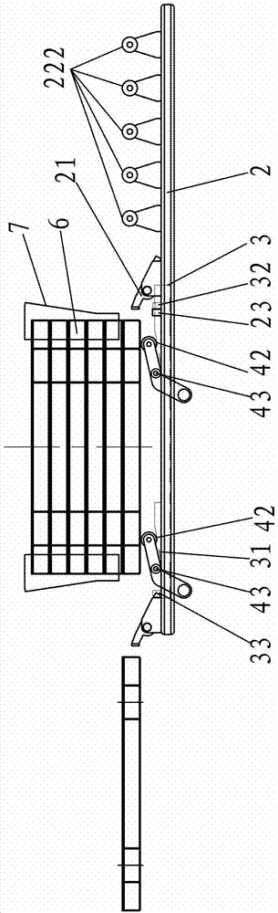
[0041] Such as Figure 1-2 Shown is a pallet separation device related to the present invention, including a base 1 and a movable frame 2 arranged on the base 1, two adjustment rails 3, a second support part 4 and an oil cylinder 5; the pallet 6 is on the base 1 Separation is carried out, and the direction in which the tray 6 is pushed out (the direction of the arrow among the figures) is the direction from back to front.

[0042] The movable frame 2 is placed on the base 1, and is driven by the oil cylinder 5 to move back and forth. The upper surface of the movable frame 2 protrudes forward and backward and is provided with a push plate part 21 and a first support part 22. The following is based on the preset stacked trays 6 to be separated, and the height of the push plate part 21 is between the penultimate ...


PUM


Abstract

The invention discloses a tray separation device, which comprises a base, a movable frame and two regulating rails, wherein the movable frame and the two regulating rails are arranged on the base, the movable frame does forward and backward movement on the base, a tray pushing part and a first support part are convexly arranged on the upper surface of the movable frame, the two outer sides of the movable frame are respectively and convexly provided with position limiting blocks in relative arrangement, the two regulating rails respectively extend in forward and backward directions and are respectively and movably erected at the two sides of the movable frame, the inner sides of the two regulating rails are respectively and convexly provided with a first regulating block and a second regulating block in forward and backward arrangement, the position of the position limiting block is limited between the first regulating block and the second regulating block, at least two inclined surfaces are respectively formed at the front and back parts on the upper surfaces of the two regulating rails, a second support part is arranged on the base in a way of corresponding to the position beside each inclined surface, and regulating shafts are horizontally and convexly arranged at the inner sides of the second support parts. Compared with the prior art, the tray separation device has the advantages that the hard friction problem in the tray separation is greatly reduced, the separation operation is stable and reliable, the separation efficiency is high, and the tray separation device is applicable to various kinds of products requiring the separation operation.

Description

technical field [0001] The invention relates to the field of block forming equipment, in particular to a pallet separating device. Background technique [0002] The block forming process includes a series of steps, involving the operation of pallets and bricks, including the separation of bricks and pallets, the stacking of bricks and pallets, and the separation of stacked bricks and pallets. The pallet separation method is generally In order to pull out or push out the bottom tray one by one, the current tray separation device is generally a simple push-out mechanism, which directly pulls out or pushes out the bottom tray by force. There is a lot of friction, and the unseparated pallet located on the bottom pallet is also in an unstable state during the whole process, which will cause damage to the pallet and reduce the service life. The pallet falls directly on the support platform, causing large vibrations, and the separation action is unreliable and unstable. [0003] ...

Claims


Application Information

Patent Timeline
Patent Type & Authority Patents(China)
IPC IPC(8): B65G59/06
Inventor 傅志昌傅清江王生劳章贤献王志生许赫正傅金山
Owner 深圳市土世界环保科技工程有限公司
Why Eureka
Try Eureka