
Follow-up support device

A supporting device and follow-up technology, which is applied in the directions of ground installation, transportation and packaging, and aircraft component testing, etc., can solve the problems of not being able to limit the deformation of the test piece, affecting the effectiveness of the test, and the safety of the test piece, so as to achieve reliability assurance and support Accurate status and improved test accuracy

Active Publication Date: 2013-04-03
CHINA AIRPLANT STRENGTH RES INST
View PDF5 Cites 13 Cited by
  • Summary
  • Abstract
  • Description
  • Claims
  • Application Information

AI Technical Summary

Problems solved by technology

[0003] In the existing aircraft structure tests, the support method of the test piece is generally suspended static support, and the vertical support method is usually used to suspend the test piece by means of suspension support or crowbar-column support. During the test loading process, the restraint points cannot limit the For the vertical restraint point, the vertical support device cannot produce additional heading and lateral constraints on the test piece due to the deformation of the test piece during the test loading process
The existing vertical support device should avoid additional constraints on the test piece during the test loading process. In theory, there is no limit to increase the vertical distance between the support point of the device and the restraint point of the test piece, but it is limited by the height of the laboratory building and the support device. Due to the limitations of strength and on-site installation space, the vertical support device can only reduce the impact of additional constraints on the test by increasing the vertical distance between the device support point and the restraint point in a limited space
Therefore, the existing vertical support device will inevitably produce additional heading and lateral constraints on the test piece during the test loading process, which directly affects the effectiveness of the test and the safety of the test piece

Method used


Image

  • Follow-up support device
  • Follow-up support device
  • Follow-up support device

Examples


Embodiment Construction

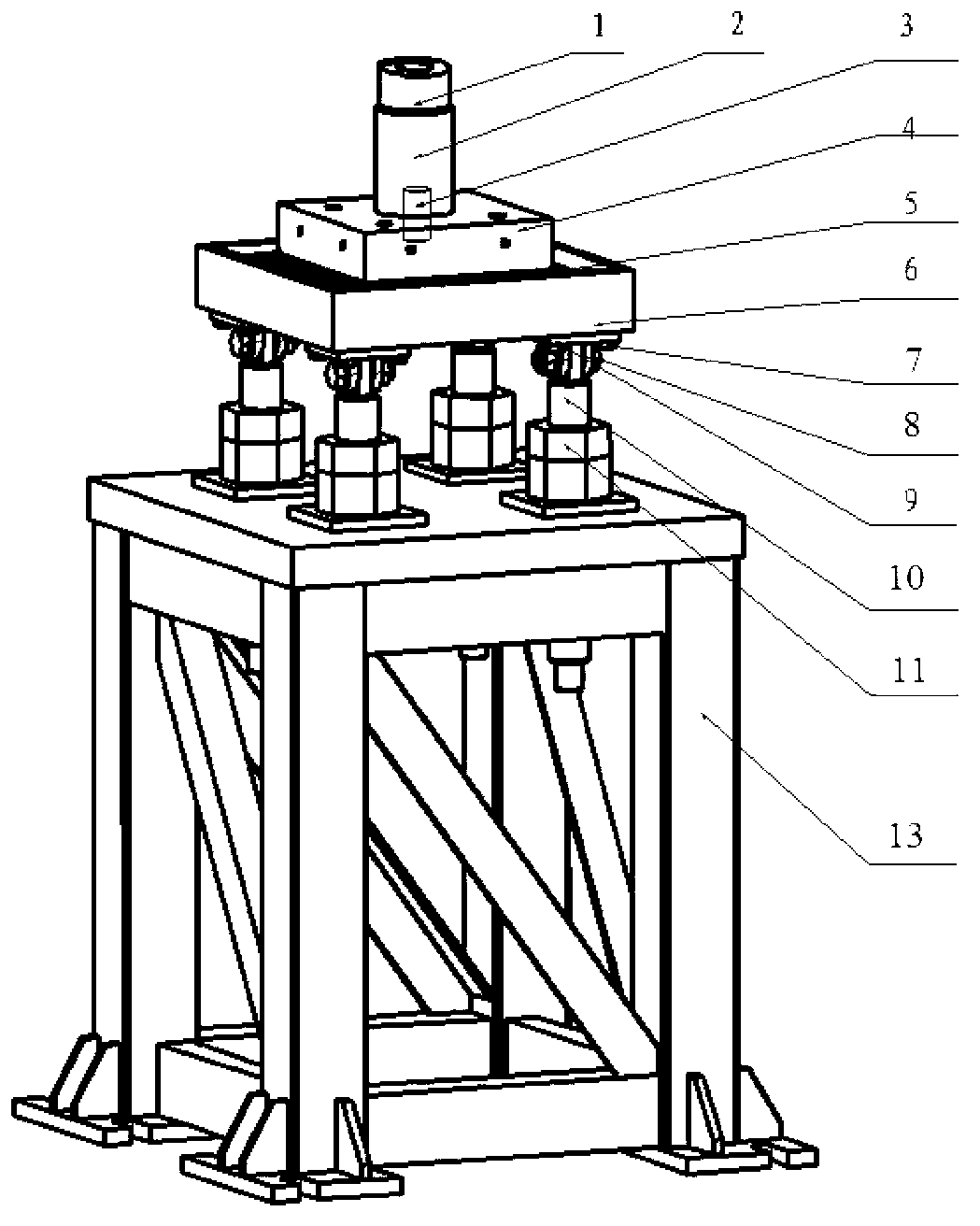
[0021] Such as figure 1 , figure 2 , image 3 As shown, the follow-up support device of the present invention includes special parts 1, a sensor 2, a connecting screw 3, a moving plate 4, a ball device 5, a fixing plate 6, a binaural fixing screw 7, a binaural 8, a hinge screw 9, and an adjusting screw 10. , The upper end adjusting nut 11, the lower end adjusting nut 12, and the mounting base 13. The ball device is composed of steel balls 14 and steel ball brackets 15. The special piece 1 is a cylindrical structure for screwing with the upper end of the sensor 2. The lower end of the sensor 2 and the upper end of the moving plate 4 are screwed together by a connecting screw 3, and the moving plate 4 and the fixed plate 6 are supported by steel balls 14 arranged in a matrix. The steel ball 14 is placed in the steel ball mounting groove / hole of the steel ball bracket 15 to ensure that the relative position of the steel ball 6 remains unchanged when the flat rolling bearing is ...


PUM


Abstract

The invention relates to a support device, in particular to a follow-up support device, which is used for airplane structure testing and can release the specific direction constraint. The follow-up support device comprises a special element, a force sensor, a connecting screw rod, a moving plate, a rolling ball device, a fixing plate, a double-lug fixing screw, double lugs, a hinging screw, a screw rod, an upper end regulating screw nut, a lower end regulating screw nut and an installing base. The follow-up support device utilizes the plane rolling bearing application principle for realizing the follow-up support function of the support device, so the support device provides the vertical support function in the testing loading process, meanwhile, the support device can be prevented from generating the additional course and the lateral restraint, and the testing precision of the airplane structure is improved. Meanwhile, the follow-up support device adopts four groups of screw rod and screw nut mechanisms in symmetrical distribution for realizing the integral height and planeness regulation of the support device, the regulation mode is simple, in addition, a regulating mechanism has a self locking function, and the support reliability of the follow-up support device can be guaranteed.

Description

Technical field [0001] The invention relates to a supporting device, in particular to a follow-up supporting device used for aircraft structure tests and capable of releasing specific direction constraints. Background technique [0002] The support program of the test piece in the aircraft structure test is directly related to the test quality and the validity of the test results. Therefore, choosing a reasonable support program and appropriate support device is the key to completing the aircraft structure test with high precision and high quality. [0003] In the existing aircraft structure test, the support method of the test piece is generally suspended statically determinate support, and the vertical direction is usually through the suspension support method or the crowbar-column support method to make the test piece hang in the air. The restraint point cannot restrict the test piece during the test loading process. For the vertical restraint point, the vertical support device ...

Claims


Application Information

Patent Timeline
Patent Type & Authority Applications(China)
IPC IPC(8): B64F5/00B64F5/60
Inventor 杜星张辛瑞余寅强韩凯盛锴张宁
Owner CHINA AIRPLANT STRENGTH RES INST
Learn More