
Variable-input three-dimensional spatial motion vibrating screen mechanism

A three-dimensional space, vibrating screen technology, applied in the direction of filter screen, solid separation, grille, etc., can solve the problems of insufficient material turnover, complex structure, and screen hole jamming

Inactive Publication Date: 2013-04-03
CHANGZHOU UNIV
View PDF4 Cites 10 Cited by
  • Summary
  • Abstract
  • Description
  • Claims
  • Application Information

AI Technical Summary

Problems solved by technology

[0002] At present, the most typical traditional vibrating screens are mainly circular vibrating screens and linear vibrating screens. Vibrations are generated by inertial vibrators, and the structure is complex. Insufficient turnover of materials, sieve holes are easily stuck by "sieve grains", resulting in low screening efficiency
[0003] Patent application number 2006100881264 provides a two-degree-of-freedom space mechanism for parallel motion equipment. The output motion of the platform is one translation and two rotations, and one of the motions is non-independent and non-controllable. In this way, In the case where three independent degrees of freedom are required, the mechanism cannot complete the corresponding work. Therefore, in order to meet the development and practical application of parallel motion equipment with different needs, a parallel vibrating screen mechanism with three independent degrees of freedom must be provided.

Method used


Image

  • Variable-input three-dimensional spatial motion vibrating screen mechanism
  • Variable-input three-dimensional spatial motion vibrating screen mechanism

Examples


Embodiment Construction

[0008] The technology of the present invention will be further described below by means of accompanying drawings and examples.

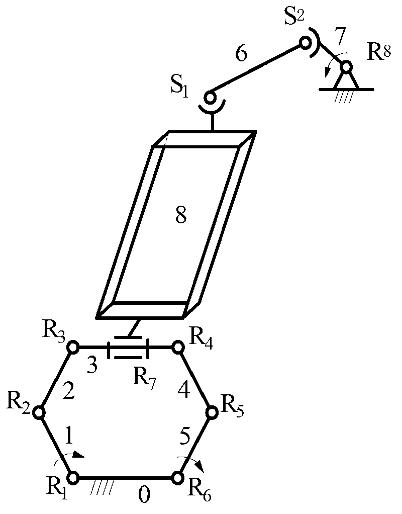
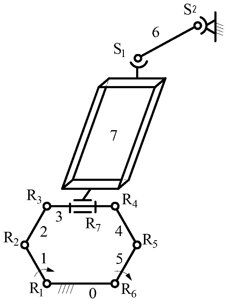
[0009] attached figure 1 It is a structural schematic diagram of an embodiment of the present invention, which includes a screen frame 8, a frame 0, a plane six-bar mechanism, a space branch chain, and six components of the plane six-bar mechanism, namely component one 1 to component six 0, Respectively use the rotating pair R with axes parallel to each other 2 ~rotational pair six R 6 Connect sequentially, take component six among them as frame 0, component three 3 and screen frame 8 opposite to frame 0 use rotating pair seven R 7 Connection; one end of the component seven 6 of the space branch chain is connected with a ball pair one S 1 Connect the screen frame 8, and the other end is connected with the ball pair S 2 Connect one end of member eight 7, and the other end of member eight 7 is rotated by eight R 8 Connect the frame 0; the three co...


PUM


Abstract

The invention discloses a variable-input three-dimensional spatial motion vibrating screen mechanism, which comprises a screen frame (8), a rack (0), a flat surface six-bar mechanism and a spatial branched chain, and is characterized in that six constructional elements of the flat surface six-bar mechanism, namely a constructional element 1 to a constructional element 6, are connected by a revolute pair 1 to a revolute pair 6 of which the axes are parallel in sequence; the constructional element 6 is taken as the rack (0); the constructional element 3 opposite to the rack (0) and the screen frame (8) are connected through a revolute pair 7 (R7) of which the axis is parallel to the axis of the constructional element 3; one end of the constructional element 7 (6) of the spatial branched chain is connected with the screen frame (8) by a ball pair 1 (S1); the other end of the constructional element 7 of the spatial branched chain is connected with one end of a constructional element 8 (7) through a ball pair 2 (S2); the other end of the constructional element 8 (7) is connected with the rack (0) through a revolute pair 8 (R8); three constructional elements connected with the rack (0) are drive rods; and when the movement of the three drive rods on the rack is controlled, the screen frame (8) can acquire one horizontal movement and two rotational outputs. The variable input three-dimensional spatial motion vibrating screen mechanism is simpler in structure and is easy to manufacture and process.

Description

technical field [0001] The invention relates to a three-dimensional motion vibrating screen mechanism, in particular, it provides a new type of three-dimensional motion mechanism for parallel structure parallel motion vibrating screens, parallel motion entertainment equipment, parallel robots and the like. Background technique [0002] At present, the most typical traditional vibrating screens are mainly circular vibrating screens and linear vibrating screens. Vibrations are generated by inertial vibrators, and the structure is complex. Insufficient turnover of materials, the sieve holes are easily stuck by "sieve grains", resulting in low screening efficiency. [0003] Patent application number 2006100881264 provides a two-degree-of-freedom space mechanism for parallel motion equipment. The output motion of the platform is one translation and two rotations, and one of the motions is non-independent and non-controllable. In this way, In the case where three independent degr...

Claims


Application Information

Patent Timeline
IPC IPC(8): B07B1/28B07B1/42
Inventor 沈惠平王振陆雁翎朱小蓉唐琳杨廷力
Owner CHANGZHOU UNIV
Learn More