
Bleeding circuit and related method for preventing improper dimmer operation

A technology of discharging circuit and discharging current, applied in the field of light source control, can solve the problems of increasing power loss, not

Active Publication Date: 2013-03-27
SIGNIFY HLDG BV
View PDF6 Cites 55 Cited by
  • Summary
  • Abstract
  • Description
  • Claims
  • Application Information

AI Technical Summary

Problems solved by technology

However, this approach results in increased power loss and is therefore not an attractive solution

Method used


Image

  • Bleeding circuit and related method for preventing improper dimmer operation
  • Bleeding circuit and related method for preventing improper dimmer operation
  • Bleeding circuit and related method for preventing improper dimmer operation

Examples


Embodiment Construction

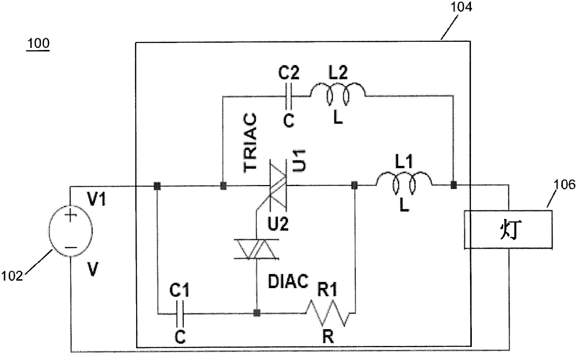
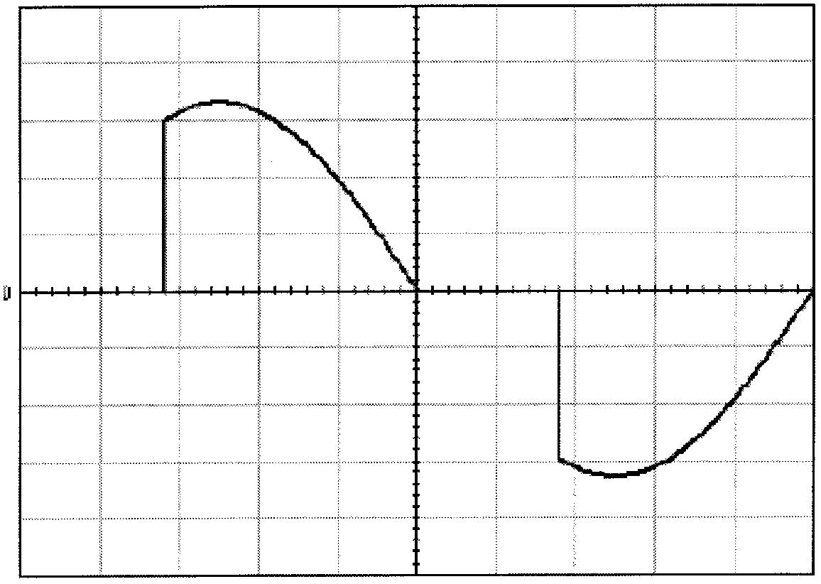
[0031] In general, the Applicant has recognized and appreciated that it is advantageous to ensure that the minimum value of the oscillatory input current of a dimmer is greater than the holding current of the dimmer. By adding a DC bias to the harmonics at the dimmer's input when the dimmer fires, the lowest value of the oscillating input current can be increased to a higher value so that the oscillating current remains above the holding current, thus Multiple triggering of the dimmer and resulting flickering of the light source is avoided. In view of the above, various embodiments and implementations of the present invention are directed to a bleeder circuit and method of eliminating flicker in which the bleeder current is controlled to be maintained until the oscillation of the input current of the dimmer ceases.

[0032] Figure 4 is a block diagram of a representative embodiment of the lighting system. see Figure 4 , the lighting system 400 includes a dimmer 404 connec...


PUM


Abstract

Disclosed are a method and apparatus for controlling bleed current, to provide the bleed current until ringing of input current at a dimmer has ceased in order to prevent misfiring of a dimmer and flicker of the light source. The return path current to the dimmer is boosted by the bleed current to be at a level greater than the holding current of the dimmer. As a result, the load current of the dimmer is increased to a sufficient minimum so that the dimmer can operate properly.

Description

technical field [0001] The present invention generally focuses on the control of light sources. More particularly, disclosed herein are various inventive methods and apparatus related to preventing flickering of light sources caused by improper triggering of dimmers Background technique [0002] Digital lighting technology, that is, lighting based on semiconductor light sources such as light-emitting diodes (LEDs), offers a viable alternative to traditional fluorescent, high-pressure discharge (HID) and incandescent lamps. The functional advantages and benefits of light emitting diodes include high energy conversion and light efficiency, durability, low operating costs and many others. Recent advances in light emitting diode technology have provided efficient and robust full-spectrum light sources capable of producing a variety of lighting effects in many applications. Some optical devices incorporating these light sources feature a lighting module that includes one or mor...

Claims


Application Information

Patent Timeline
IPC IPC(8): H05B33/08H05B44/00
CPCH05B33/0809H05B45/3575H05B45/3725
Inventor 关振源乔海波彭超
Owner SIGNIFY HLDG BV
Learn More