
LED lamp protection circuit

A technology for LED lamps and protection circuits, applied in the electronic field, can solve problems such as LED lamp damage, unfavorable economic benefits, and LED lamps have no protective effect, and achieve the effect of reducing the amount of current

Inactive Publication Date: 2013-03-27
XUZHOU GLORIA TECH
View PDF0 Cites 1 Cited by
  • Summary
  • Abstract
  • Description
  • Claims
  • Application Information

AI Technical Summary

Problems solved by technology

[0002] With the development of society, LED lamps have become the main fluorescent lamps in the market due to their energy saving and environmental protection, and are accepted by consumers. When it is too large, it is easy to cause damage to the LED lamp, resulting in waste of resources and increased costs, which is not conducive to improving economic benefits

Method used


Image

  • LED lamp protection circuit

Examples


Embodiment Construction

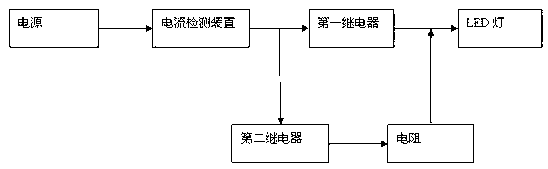
[0008] The present invention will be described below in conjunction with the accompanying drawings and embodiments.

[0009] like figure 1 As shown, the present invention is composed of a power supply, an LED lamp, a current detection device, a relay and a resistor, the power supply is electrically connected to the input end of the current detection device, the output end of the current detection device is electrically connected to the first relay input end, and the first relay output end is The input end of the LED lamp is electrically connected, and after the resistor is connected in series with the second relay, one end is connected between the current detection device and the relay, and the other end is connected between the relay and the LED lamp;

[0010] The power supply is a mains power supply or a battery;

[0011] The resistor is a variable resistor.

[0012] During implementation, after the power supply is powered on, the current detection device starts real-time ...


PUM


Abstract

The invention discloses an LED lamp protection circuit and belongs to the technical field of electronics. The LED lamp protection circuit comprises a power source, an LED lamp, a current detecting device, relays and a resistor. The power source is electrically connected with an input end of the current detecting device, an output end of the current detecting device is electrically connected with the first relay, an output end of the first relay is electrically connected with an input end of the LED lamp, one end of the resistor is connected between the current detecting and the relays after the resistor is connected with the second relay serially, and the other end of the resistor is connected between the relays and the LED lamp. The current detecting device is added, when current is too high, the current detecting device can control the current to flow through the resistor and flow through the LED lamp through the resistor, current of the LED lamp is reduced, and the LED lamp is protected.

Description

technical field [0001] The invention relates to an LED lamp circuit, in particular to an LED lamp protection circuit, which belongs to the field of electronic technology. Background technique [0002] With the development of society, LED lamps have become the main fluorescent lamps in the market due to their energy saving and environmental protection, and are accepted by consumers. When it is too large, it is easy to cause damage to the LED lamp, resulting in waste of resources and increased costs, which is not conducive to improving economic benefits. Contents of the invention [0003] The purpose of the present invention is to provide a LED lamp protection circuit, which can detect the flow of the circuit and reduce the current to play a protective role. [0004] In order to achieve the above object, the technical solution adopted in the present invention is: the LED lamp protection circuit includes a power supply and an LED lamp, and also includes a current detection d...

Claims


Application Information

Patent Timeline
IPC IPC(8): H05B37/00
Inventor 侯光辉
Owner XUZHOU GLORIA TECH
Learn More