Method for producing scintillator arrays with silver (ag) based gaps

A scintillator and gap technology, applied in the field of scintillators, can solve problems such as damage to glue and damage

Active Publication Date: 2015-11-25
KONINKLIJKE PHILIPS ELECTRONICS NV
View PDF7 Cites 0 Cited by
  • Summary
  • Abstract
  • Description
  • Claims
  • Application Information

AI Technical Summary

Problems solved by technology

Unfortunately, such temperatures will damage and destroy the glue that holds the array together

Method used


Image

  • Method for producing scintillator arrays with silver (ag) based gaps
  • Method for producing scintillator arrays with silver (ag) based gaps
  • Method for producing scintillator arrays with silver (ag) based gaps

Examples


Embodiment Construction

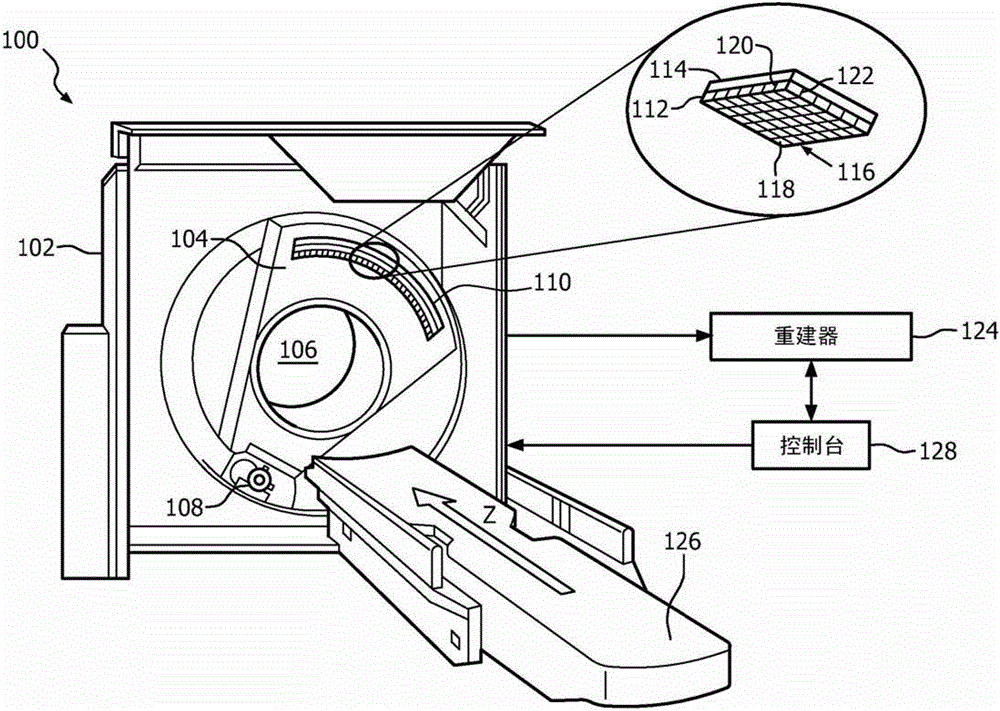
[0014] figure 1 An imaging system 100 is shown, such as a computed tomography (CT) system, including a stationary gantry portion 102 and a rotating gantry portion 104 . The rotating gantry section 104 is rotatably supported by the stationary gantry section 102 and is configured to rotate about an inspection region 106 about a longitudinal or z-axis. The rotating gantry section 104 supports an X-ray source 108 , such as an X-ray tube, which rotates with the rotating gantry section 104 about the examination region 106 and emits radiation that penetrates the examination region 106 .

[0015] The radiation sensitive detector array 110 includes a plurality of scintillator arrays 112 each optically coupled to a photosensor array 114 . Each scintillator array 112 detects radiation penetrating the examination region 106 and generates a light signal indicative of the detected radiation, while the photosensor array 114 receives the light and generates a signal indicative of the light a...


PUM


Abstract

A method includes obtaining a plurality of the two dimensional arrays of gadolinium oxysulfide. An array has wider width non-silver based spacers (304) that extend between rows or columns of dixels and narrower width non-silver based spacers (306) that extend between the other of the rows or columns of dixels. The method further includes applying a silver coating (312) to at least one of a top or bottom surface of the arrays. The method further includes forming a stack by stacking the silver coated arrays, one on top of another (FIG. 3B), with substantially equal layers of adhesive between adjacent arrays. The method further includes slicing the stack through the wider non-silver based spacers to form two dimensional arrays of scintillator dixels (314) having silver based spacers (312) along at least one direction of the array.

Description

technical field [0001] The present invention relates generally to scintillators, and in particular to a method of producing a scintillator array with silver (Ag) based gaps along at least one direction of the scintillator array. The scintillator array can be used in various imaging modalities such as computed tomography (CT), X-ray and / or other imaging modalities. Background technique [0002] A computed tomography (CT) system includes a radiation source that rotates about an examination region and emits radiation that penetrates the examination region, and an array of radiation-sensitive detectors that detects radiation that penetrates the examination region. The detector array already includes a scintillator array coupled to the photosensor array. The scintillator array receives radiation and converts it to light indicative of the radiation, while the photosensor array receives the light and generates electrical signals indicative thereof. The signal can be reconstructed...

Claims


Application Information

Patent Timeline
Patent Type & Authority Patents(China)
IPC IPC(8): G01T1/20
CPCA61B6/40A61B6/032A61B6/4233G01T1/2002G10K15/00Y10T156/1002Y10T156/1052Y10T156/1043
Inventor S·莱韦内
Owner KONINKLIJKE PHILIPS ELECTRONICS NV
Why Eureka
Try Eureka