Diaphragm detection jig used for liquid crystal display module

A liquid crystal display module and detection fixture technology, which is applied in the direction of testing optical properties, optics, instruments, etc., can solve the problems of cumbersome operation, long time, and aggravated material loss, so as to improve verification efficiency, reduce material loss, and save cost effect

Inactive Publication Date: 2013-03-20
AU OPTRONICS (XIAMEN) CORP +1
View PDF0 Cites 7 Cited by
  • Summary
  • Abstract
  • Description
  • Claims
  • Application Information

AI Technical Summary

Problems solved by technology

[0004] However, in the internal structure of a traditional liquid crystal display device, when replacing each optical film, it is necessary to remove the front frame, the middle frame and the liquid crystal panel each time, and then reinstall the liquid crystal panel, the middle frame and the front frame after the replacement. Complicated, the whole replacement process takes a long time
On the other hand, if the verification carrier of the ring test project of the optical film is a finished liquid crystal panel, because the gap between each material in the finished product is affected by its own cutting size and assembly, it usually cannot truly reflect the design value
Moreover, verified materials cannot be reused, which increases material loss and increases verification costs

Method used


Image

  • Diaphragm detection jig used for liquid crystal display module
  • Diaphragm detection jig used for liquid crystal display module

Examples


Embodiment Construction

[0020] In order to make the technical content disclosed in this application more detailed and complete, reference may be made to the drawings and the following various specific embodiments of the present invention, and the same symbols in the drawings represent the same or similar components. However, those skilled in the art should understand that the examples provided below are not intended to limit the scope of the present invention. In addition, the drawings are only for schematic illustration and are not drawn according to their original scale.

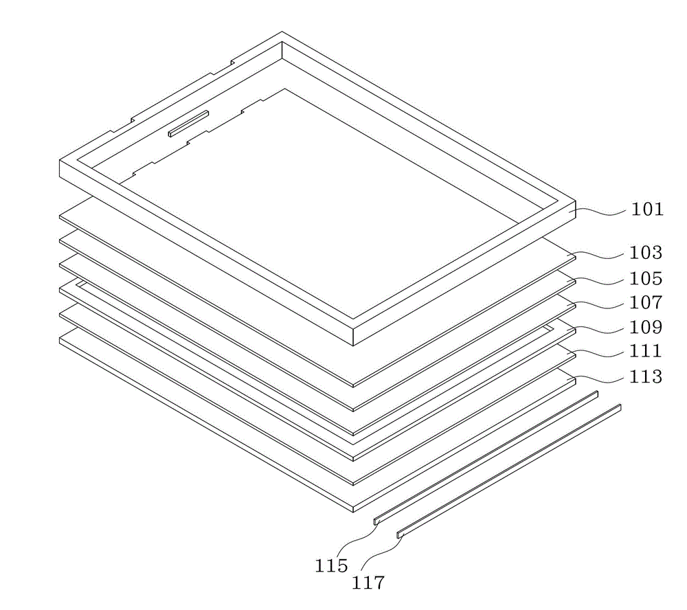
[0021] figure 1 It shows a structural schematic diagram of the ring test verification of the diaphragm in the liquid crystal display module in the prior art.

[0022] As mentioned earlier, when developing different types of liquid crystal display devices (such as low power consumption, high brightness, ultra-thin, etc.) according to different application requirements, it is necessary to evaluate their optical indicators, especia...


PUM


Abstract

The invention provides a diaphragm detection jig used for a liquid crystal display module. The diaphragm detection jig comprises a first side edge, a second side edge and a plurality of through holes. The inner wall of the first side edge is provided with a plurality of first lug bosses and first gaps are arranged between the adjacent first lug bosses. The second side edge is parallel to the first side edge; the inner wall of the second side edge is provided with a plurality of second lug bosses, second gaps are arranged between adjacent lug bosses, and one or a plurality of optical diaphragms to be detected are put through the first and second gaps. All the through holes are located between the first gaps and the inner wall of the first side edge and are used for inserting strip heat sources. According to the invention, optical diaphragms are set corresponding to the first gaps of the first lug bosses and the second gaps of the second lug bosses, then the strip heat sources are inserted into the through holes beside the first gaps, and in such a way, the loop test and checking to the diaphragm materials are realized. Compared with the prior art, the diaphragm detection jig can test and compare various optical diaphragms which are made of different materials, and the diaphragm detection jig saves cost, reduces the material loss and improves the checking efficiency.

Description

technical field [0001] The invention relates to a liquid crystal display module, in particular to a diaphragm detection fixture of the liquid crystal display module. Background technique [0002] At present, liquid crystal display devices, such as liquid crystal televisions and liquid crystal monitors, have been widely used due to their thin body, low radiation, high-definition display and many other advantages. However, the liquid crystal panel in the liquid crystal display device cannot emit light by itself, and usually needs to use a backlight source as a lighting power source. Moreover, in order to obtain a good display effect, various optical films need to be installed between the backlight source and the liquid crystal panel, such as diffusion plates, diffusion sheets, and enhancement films, etc. These optical films can transmit and diffuse the light emitted by the backlight source. , to improve the brightness, uniformity and chromaticity of light and other indicators...

Claims


Application Information

Patent Timeline
IPC IPC(8): G02F1/13G01M11/02
Inventor 孙赓楠卢仁生
Owner AU OPTRONICS (XIAMEN) CORP
Why Eureka
Try Eureka