Eureka AIR delivers breakthrough ideas for toughest innovation challenges, trusted by R&D personnel around the world.

Planetary concrete mixer

A concrete mixer, planetary technology, applied in cement mixing devices, clay preparation devices, chemical instruments and methods, etc., can solve problems affecting the workability, strength and durability of concrete, cement particles are not uniformly dispersed, blades Complex structure and other problems, to achieve the effects of easy popularization, enhanced relative mobility, and low cost

Inactive Publication Date: 2013-03-20
CHANGAN UNIV
View PDF10 Cites 13 Cited by
  • Summary
  • Abstract
  • Description
  • Claims
  • Application Information

AI Technical Summary

Problems solved by technology

In the prior art, the blade structure of the ordinary vertical shaft planetary mixer is relatively complicated, the mixing wear is large, and there are strict restrictions on the particle size of the aggregate
It can generally make the mixed concrete macroscopically uniform in a short period of time, but if the cement slurry in the macroscopically homogeneous concrete after mixing is observed under a microscope, it will be found that the cement particles are not evenly dispersed in the water. , 10% to 30% of the cement particles gather together in twos and threes to form tiny cement clusters, which affect the workability, strength and durability of concrete.
In recent years, some solutions to this problem have been proposed at home and abroad. For example, many people have studied the design and arrangement of mixing blades, so as to improve the microscopic uniformity of concrete through repeated mixing without dead zones, but the results have not been proved by experiments. not obvious

Method used


Image

  • Planetary concrete mixer
  • Planetary concrete mixer

Examples


Embodiment Construction

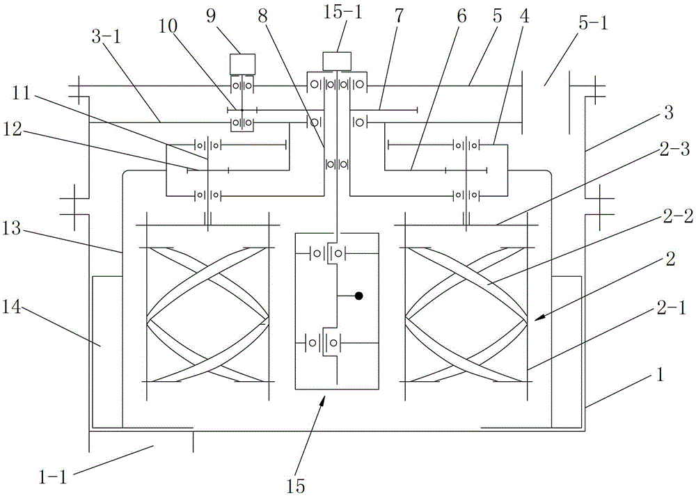
[0032] like figure 1 A planetary concrete mixer shown includes a lower cylinder 1 and a plurality of ribbon stirring devices 2 arranged inside the lower cylinder 1. The upper part of the lower cylinder 1 is connected with a middle A cylinder 3, a planetary gear mechanism is arranged in the middle cylinder 3; a cover plate 5 is arranged on the upper end of the middle cylinder 3, and a stirring drive device 9 is arranged on the cover plate 5, and the stirring drive device 9 The power output shaft passes through the cover plate 5 and extends into the middle cylinder 3, and a pinion 10 is installed at the position extending into the middle cylinder 3; the middle part of the cover plate 5 is rotatably connected with a vertically arranged stirring input shaft 8. The lower end of the stirring input shaft 8 extends into the middle cylinder 3, the large gear 7 meshing with the pinion 10 is installed on the stirring input shaft 8, and the cover plate 5 is provided with a The feed port ...


PUM


Abstract

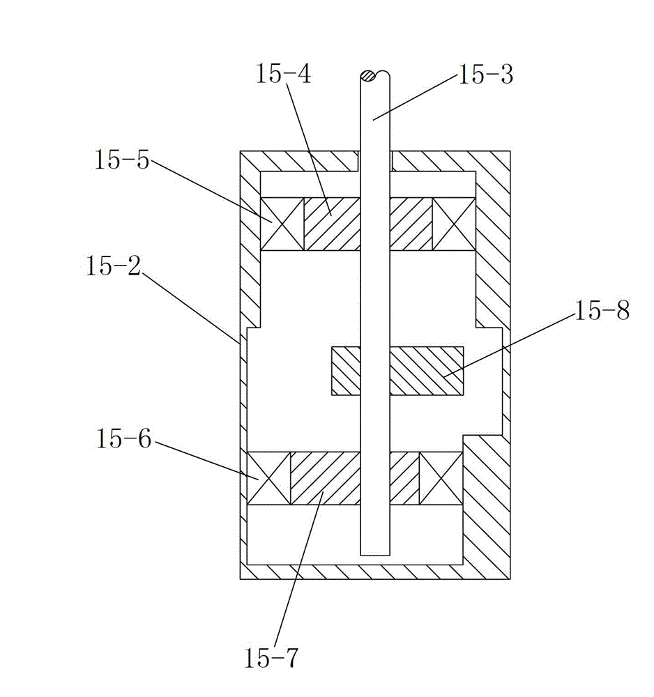
The invention discloses a planetary concrete mixer, which comprises a lower barrel body and a plurality of helical ribbon mixing devices, wherein a middle barrel body is connected to the upper part of the lower barrel body; a planetary gear mechanism is arranged in the middle barrel body; a cover plate is arranged at the upper end of the middle barrel body; a mixing drive device is arranged on the cover plate; a mixing input shaft is rotationally connected in the middle of the cover plate; the planetary gear mechanism comprises planetary racks, sun wheels and a plurality of planetary wheels; the planetary racks are connected to the lower end of the mixing input shaft; the sun wheels are sleeved on the mixing input shaft; the upper ends of the sun wheels are connected with the middle barrel body; planetary wheel shafts are arranged on the planetary racks; the planetary wheels are mounted on the planetary wheel shafts; each helical ribbon mixing device comprises two mixing arms; mixing helical ribbons are connected on the inner side surfaces of the two mixing arms; the upper parts of the two mixing arms are connected through a connecting plate; the lower ends of the planetary wheel shafts are connected with the connecting plates; and a vibration mechanism is arranged in the lower barrel body. According to the planetary concrete mixer, the microcosmic uniformity of concrete can be effectively improved.

Description

technical field [0001] The invention relates to a concrete mixer, in particular to a planetary concrete mixer. Background technique [0002] Concrete mixer is a special machine for mixing concrete batch materials evenly to make plastic concrete mixture. It is widely used in construction projects and commercial concrete factories. It is an essential machine for engineering construction. Its performance directly affects all The quality and efficiency of mixing concrete. In the prior art, the vane structure of the ordinary vertical shaft planetary mixer is relatively complicated, the mixing wear is large, and there is a strict limit on the particle size of the aggregate. It can generally make the mixed concrete macroscopically uniform in a short period of time, but if the cement slurry in the macroscopically homogeneous concrete after mixing is observed under a microscope, it will be found that the cement particles are not evenly dispersed in the water. , 10% to 30% of cement...

Claims


Application Information

Patent Timeline
Patent Type & Authority Applications(China)
IPC IPC(8): B28C5/16
Inventor 冯忠绪刘小玲姚运仕赵利军田建涛朱霖龙王艳
Owner CHANGAN UNIV
Why Eureka
Eureka Blog
Learn More