Rotor core

A technology of yoke and magnetic rotor, which is applied in the direction of magnetic circuit rotating parts, magnetic circuit shape/style/structure, electric components, etc., to achieve the effect of reducing material consumption and improving material yield

Inactive Publication Date: 2013-03-13
MOTEURS LEROY SOMER
View PDF6 Cites 0 Cited by
  • Summary
  • Abstract
  • Description
  • Claims
  • Application Information

AI Technical Summary

Problems solved by technology

This largely results in the generation of cutting waste, and thus the ratio stated above is kept well below 1

Method used


Image

  • Rotor core
  • Rotor core
  • Rotor core

Examples


Embodiment Construction

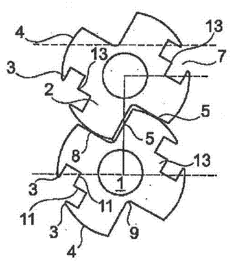
[0029] A rotor yoke frame according to the present invention, such as Figure 7 , comprising a stack of assembled magnetic plates 4, one of which is shown separately in Figure 4 middle.

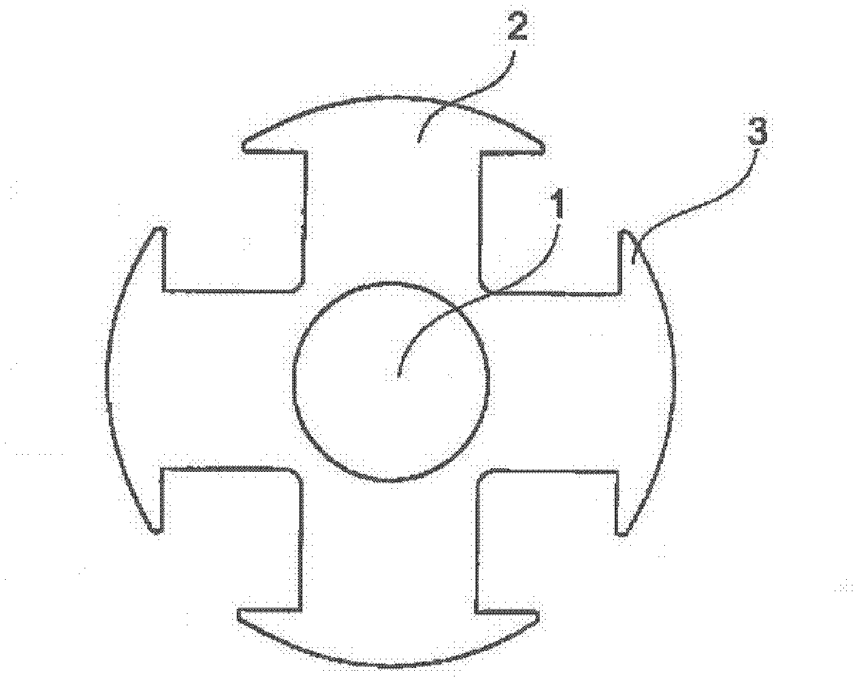
[0030] According to a preferred exemplary implementation of the invention, each plate 4 has a plurality of magnetic poles, each magnetic pole has a single pole tip 3, on the side opposite to the pole tip 3, this magnetic pole has a pole extending to the A straight edge 5 of the radially outer circumference 6 of the pole.

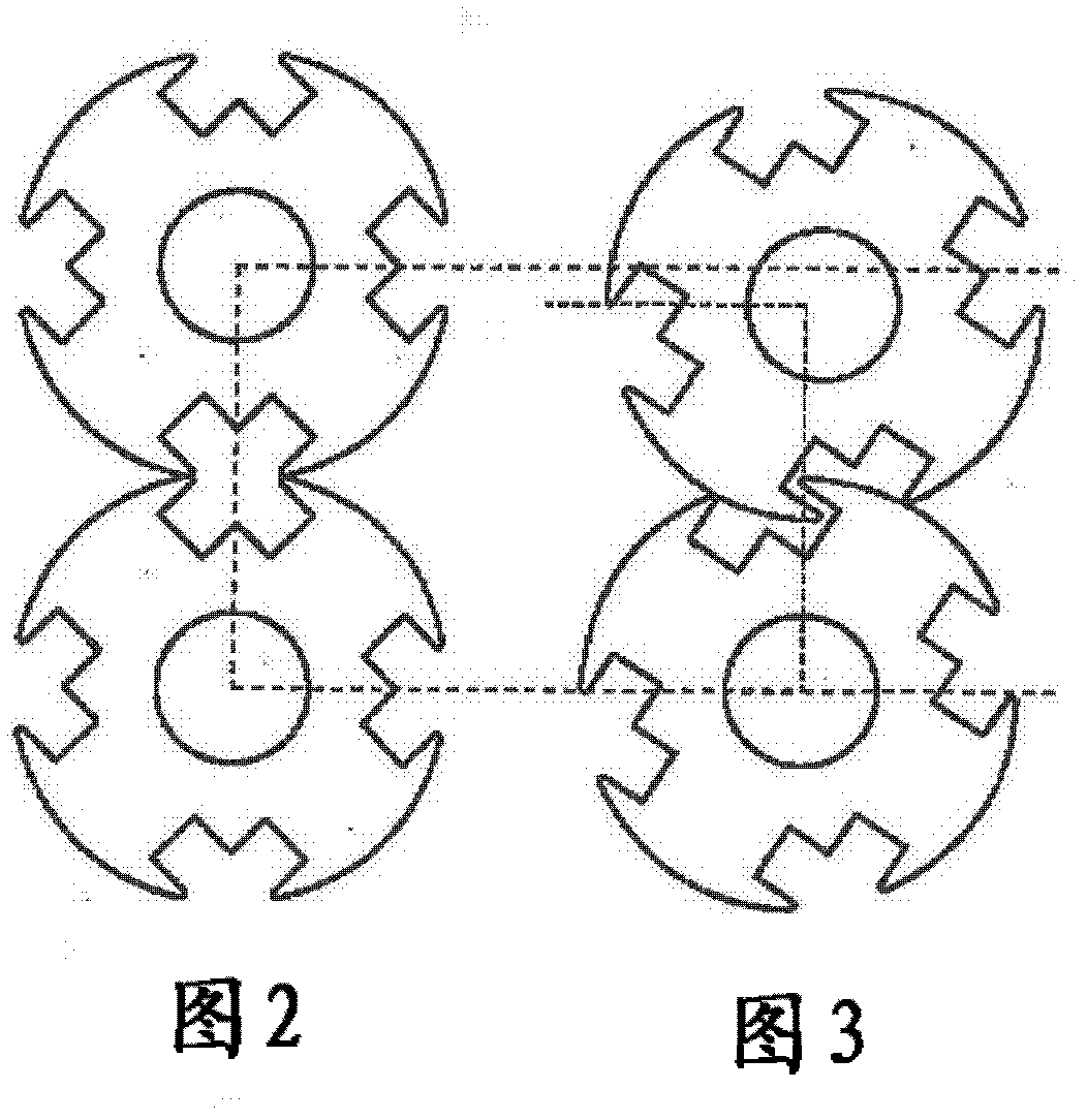
[0031] Two adjacent poles have their pole tips 3 pointing towards the same interpole space 7 , while the edges 5 without pole tips delimit a further interpole space 8 . In the example shown with four poles, one plate 4 has two diametrically opposite interpole spaces 7 and two further diametrically opposite interpole spaces 8 .

[0032] These straight edges 5 meet adjacent to the hole 1, while on the side where the pole tip 3 is present, the pole body is widened so as to...


PUM


Abstract

The invention relates to a magnetic rotor core for an electric rotary machine, comprising a stack of magnetic laminations having poles provided with pole tips (3), said core being characterised in that the stack comprises laminations of which at least one of the poles has at least one at least partially truncated pole tip, preferably a single pole tip (3).

Description

technical field [0001] The present invention relates to rotating electric machines, and more particularly to a rotor yoke frame (also referred to as a rotor body) formed from a stack of stacked magnetic plates. Background technique [0002] Conventionally, the rotating field magnet plates of a 4-pole alternator have a symmetrical outline, as illustrated in Figure 1, which outlines around a shaft hole 1 centered on the axis of rotation of the rotor To be constructed, four bodies 2 of orthogonal magnetic poles conducting magnetic flux to the stator are arranged around this shaft hole. At their ends, the pole bodies are each extended laterally by two pole tips 3 , which make it possible to spread the magnetic flux that will surround the stator. [0003] The rotating field magnetic plates are preferably obtained by cutting from steel sheets with a small thickness (from a few tenths to a few millimeters). The plates are then stacked to form a rotor yoke frame of the desired len...

Claims


Application Information

Patent Timeline
IPC IPC(8): H02K1/28
CPCH02K1/06H02K1/24H02K15/022Y10T83/04
Inventor 帕特里克·沃尔格穆特
Owner MOTEURS LEROY SOMER
Why Eureka
Try Eureka