
Image rendering method and equipment

An image rendering and pixel point technology, applied in the field of image rendering, can solve problems such as low image rendering efficiency, achieve the effect of depth of field and improve efficiency

Inactive Publication Date: 2013-03-13
HUAWEI TECH CO LTD +1
View PDF3 Cites 18 Cited by
  • Summary
  • Abstract
  • Description
  • Claims
  • Application Information

AI Technical Summary

Problems solved by technology

In this way, it is necessary to use multiple drawing scene techniques in this technology, and after multiple renderings, the efficiency of image rendering is low

Method used


Image

  • Image rendering method and equipment
  • Image rendering method and equipment
  • Image rendering method and equipment

Examples


Embodiment Construction

[0023] The following will clearly and completely describe the technical solutions in the embodiments of the present invention with reference to the accompanying drawings in the embodiments of the present invention. Obviously, the described embodiments are only some, not all, embodiments of the present invention. Based on the embodiments of the present invention, all other embodiments obtained by persons of ordinary skill in the art without creative efforts fall within the protection scope of the present invention.

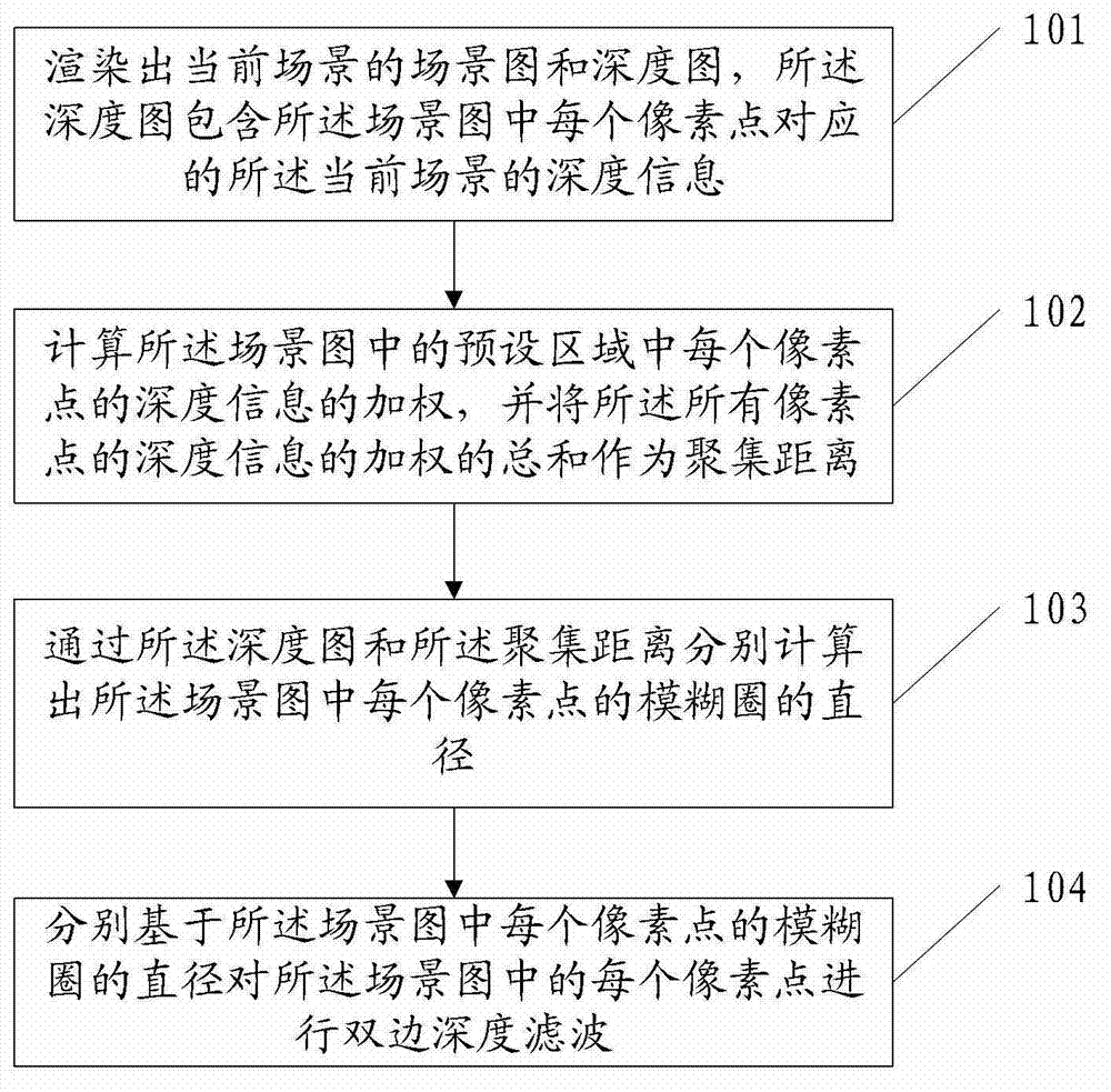
[0024] figure 1 is a schematic flowchart of an image rendering method provided by an embodiment of the present invention, such as figure 1 shown, including:

[0025] 101. Render a scene graph and a depth map of the current scene, where the depth map includes depth information of the current scene corresponding to each pixel in the scene graph;

[0026] 102. Calculate the weight of the depth information of all pixels in the preset area in the scene image, and use ...


PUM


Abstract

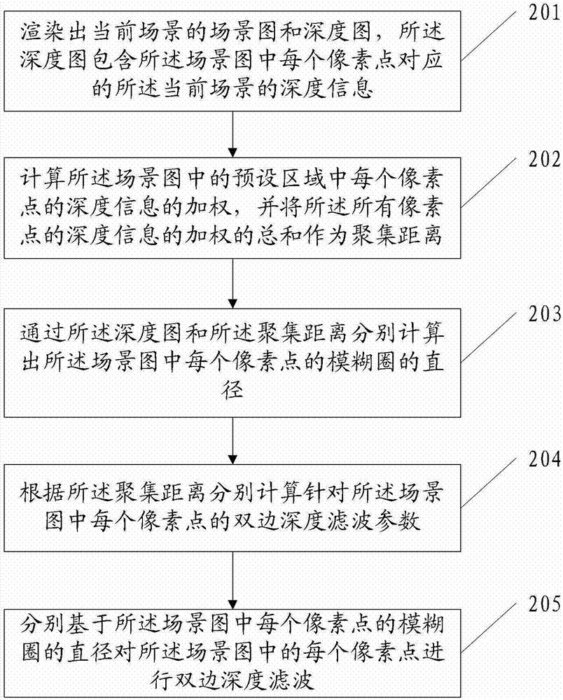
The embodiment of the invention discloses an image rendering method. The method comprises the following steps of: rendering a scene graph and a depth graph of a current scene, wherein the depth graph comprises depth information (of the current scene) corresponding to each pixel point in the scene graph; calculating the weight of the depth information of each pixel point in a preset area in the scene graph, wherein the total sum of the weights of the depth information of all the pixel points is taken as a gathering distance; respectively calculating the diameters of confusion circles of the pixel points in the scene graph by virtue of the depth graph and the gathering distance; and respectively carrying out bilateral depth filtering on each pixel point in the scene graph based on the diameter of the confusion circle of each pixel point in the scene graph. Correspondingly, the embodiment of the invention further provides image rendering equipment. The image rendering method and equipment provided by the embodiment of the invention can improve the efficiency of image rendering.

Description

technical field [0001] The present invention relates to the field of image processing, in particular to an image rendering method and device. Background technique [0002] The essence of image rendering is the real-time calculation and real-time output of graphics data. Currently, the widely used image rendering technology is online cumulative rendering technology. This technology can simulate the effect of depth of field. This technology is implemented in the way of cumulative buffering. The so-called cumulative buffering is to accumulate a series of drawing results. After all the images are rendered, the drawing results of the cumulative buffering are connected into a complete image, and The image is fed into the frame buffer and finally displayed on the screen. The pixel values ​​of the final image generated in this technique are accumulated from the pixel values ​​of the same pixel points in multiple images. In this way, it is necessary to adopt the technology of drawi...

Claims


Application Information

Patent Timeline
Patent Type & Authority Applications(China)
IPC IPC(8): G06T15/00G06T15/20
Inventor 吴尚陈玮盛斌
Owner HUAWEI TECH CO LTD
Learn More