Hydraulic well drilling, cavity drilling and hole drilling technology
A drilling and hole drilling technology, which is applied in the direction of drilling with liquid/gas jets, etc., can solve the problems of high cost, slow drilling speed, and large production equipment.
- Summary
- Abstract
- Description
- Claims
- Application Information
AI Technical Summary
Problems solved by technology
Method used
Image
Examples
example 1
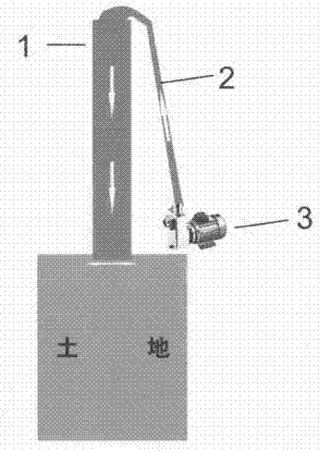
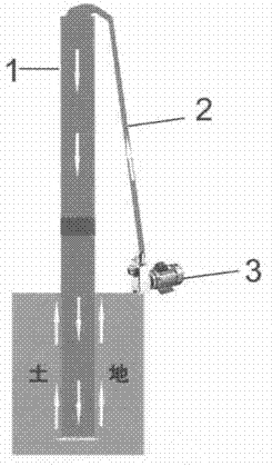
[0013] Example 1, drill a small well or cave, pump water with a water pump, the water outlet of the pump is connected to a water pipe, the water pipe is soft and hard, and the water pipe outlet is tightly pressed against the ground when drilling, as in figure 1 , the water flows forward to push away the soil, and the water pipe presses down immediately, keeping the water outlet area of the water pipe outlet small, so that the water pipe outlet maintains a high-pressure and high-speed water flow, and the soil pushed away by the water will follow the water flow back to the wellhead , the depth of the well can be deepened by repeatedly extending the water pipe, such as figure 2 , Drilling, the drilling technology is the same as the drilling technology, but the direction and size are different.
example 2
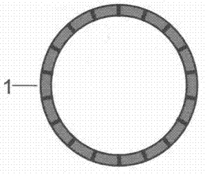
[0014] Example 2: Drilling large wells or caves, using double-layer water pipes, leaving only a small space between the pipes, the outer pipe and the inner pipe are welded together firmly, and the space between the outer pipe and the inner pipe is divided into Multiple waterways, cross-section such as image 3 , adopt multi-channel water supply, in case the soil is soft and hard, one side of the water pipe is soft and pushed away by the water, while the other side is hard and does not push away, the water pipe cannot be pushed forward, so that the water outlet area of the water outlet increases and the water flow pressure decreases ,like Figure 4 , using the space between the pipes to send water can also reduce water consumption. The large-scale drilling method is also the same as in Example 1. The water outlet presses the soil tightly, the water pushes the soil away, and the water pipe moves forward. A large amount of sediment is generated in the inner pipe. , use such as...
example 3
[0015] Example 3 The present invention is equally applicable to mountain boreholes, underground tunnel horizontal boreholes, such as Figure 5 According to different requirements, the water pipes can be replaced by other containers of various shapes, such as rectangles, squares, ovals, etc., to realize drilling wells, holes, and holes of different shapes.
[0016] In summary, compared with the existing drilling equipment, the equipment used in the present invention is greatly simplified, so that the construction cost is lower, and the work rate is higher. There is no need to add mud treatment agent for drilling, which protects the environment and can be truly environmentally friendly. work.
PUM
 Abstract
Description
Claims
Application Information
 - R&D
- Intellectual Property
- Life Sciences
- Materials
- Tech Scout
- Unparalleled Data Quality
- Higher Quality Content
- 60% Fewer Hallucinations
Browse by: Latest US Patents, China's latest patents, Technical Efficacy Thesaurus, Application Domain, Technology Topic, Popular Technical Reports.
© 2025 PatSnap. All rights reserved.Legal|Privacy policy|Modern Slavery Act Transparency Statement|Sitemap|About US| Contact US: help@patsnap.com


