
Force-increasing test apparatus for tensile strength of pull rod

A technology of tensile strength and testing equipment, which is applied in the direction of applying repeated force/pulsation force to test the strength of materials, etc., can solve the problem of not being able to judge the thread of the tie rod, and achieve the effects of size reduction, easy operation, and cost reduction

Active Publication Date: 2013-02-27
NINGBO HWAMDA MACHIENRY MFG
View PDF4 Cites 6 Cited by
  • Summary
  • Abstract
  • Description
  • Claims
  • Application Information

AI Technical Summary

Problems solved by technology

[0002] The tie rod is one of the most important parts of the injection molding machine. The material used is mostly 40Cr. It is very important that its tensile strength meets the standard. However, since the diameter of the tie rod of the injection molding machine is usually 60mm~360mm, even if the smallest diameter is 60mm If you want to test the tensile strength of the tie rod, you also need a tensile tester with a force of about 250T (such as the commonly used tensile cylinder at present). Such a powerful tensile tester is basically not available in the market.
Therefore, at present, the tensile strength test of the tie rod basically adopts a sampling test. During the test, the pull rod is turned into a sample with a diameter of 20mm for the tensile strength test, but this method cannot judge whether the thread of the tie rod is intact or whether the overall material is Qualified, so it is impossible to directly and accurately judge whether the overall tie rod is qualified

Method used


Image

  • Force-increasing test apparatus for tensile strength of pull rod
  • Force-increasing test apparatus for tensile strength of pull rod
  • Force-increasing test apparatus for tensile strength of pull rod

Examples


Embodiment Construction

[0023] The present invention will be further described in detail below in conjunction with the accompanying drawings and embodiments.

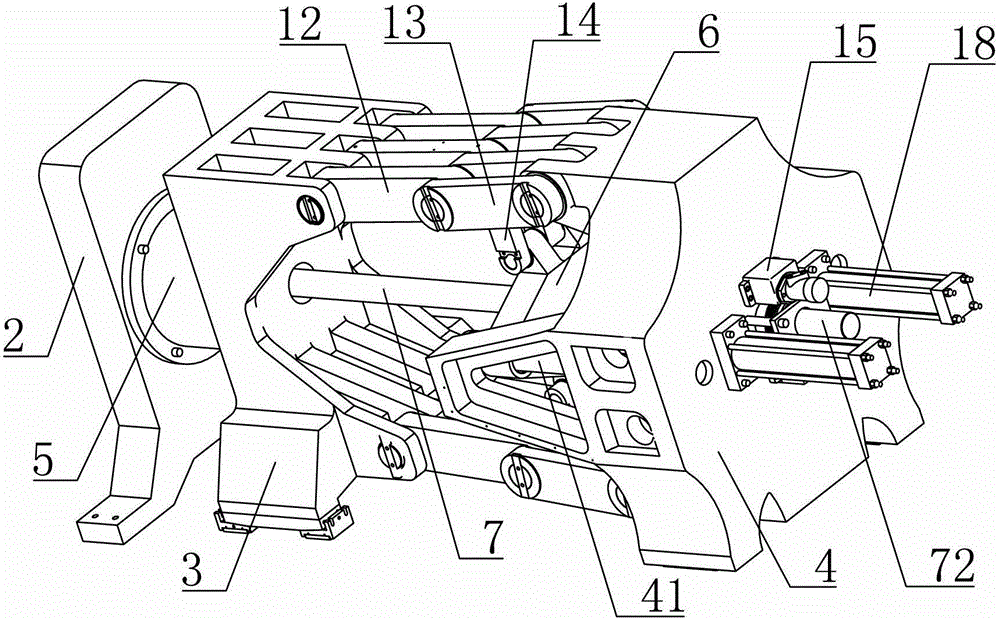
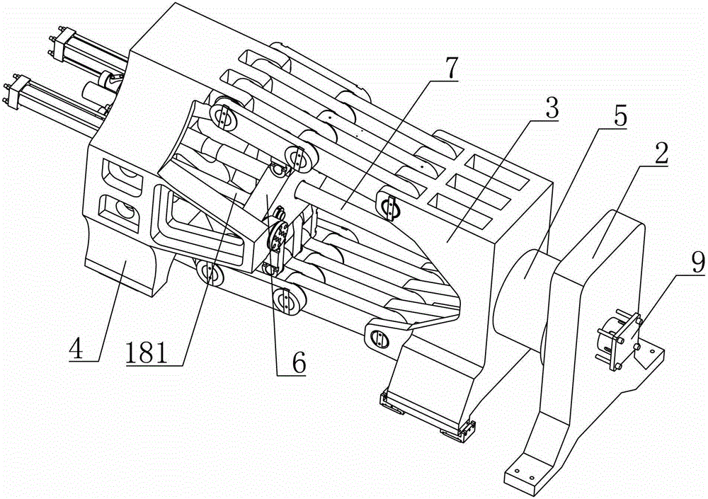
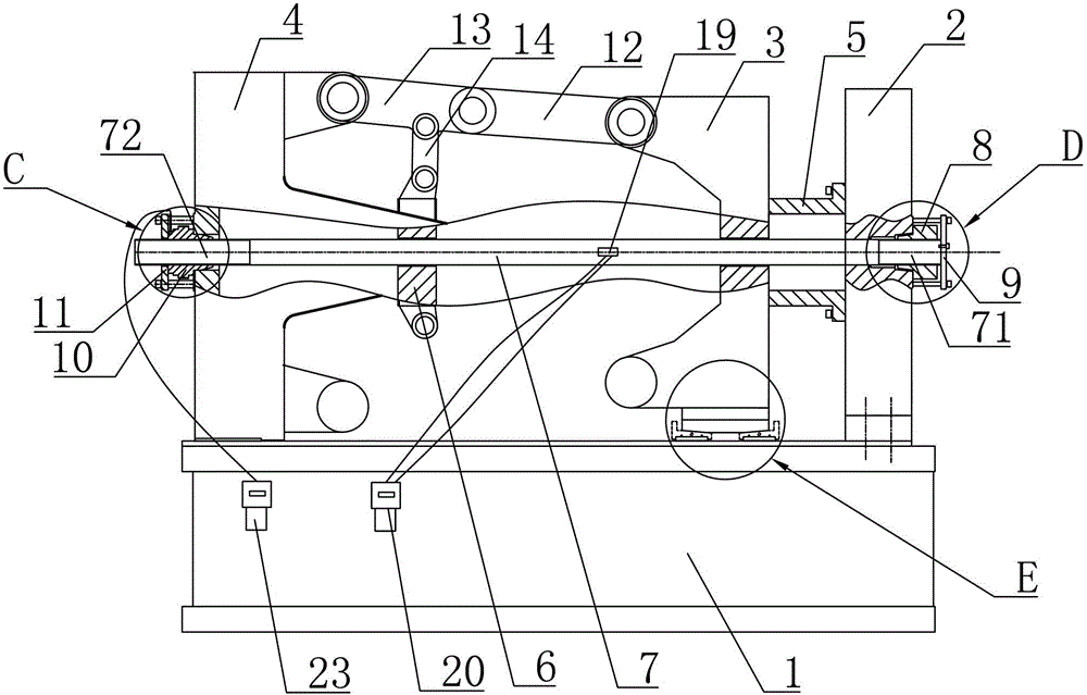
[0024] As shown in the figure, a device for testing the tensile strength of a booster pull rod includes a base 1 and a front plate 2, a middle plate 3 and a rear plate 4 arranged side by side on the base 1 in sequence. The front plate 2 and the base 1 Fixedly connected, the bottom of the middle plate 3 is provided with a sliding assembly 21, the sliding assembly 21 is horizontally slidingly matched with the base 1, the rear plate 4 is horizontally slidingly matched with the base 1, and the front plate 2 is fixedly provided with a The moving limit block 5 is provided with a thrust seat 6 between the rear plate 4 and the middle plate 3, and a thrust seat guide rod 41 is fixedly arranged on the rear plate 4 along the horizontal direction, and the thrust seat 6 is sleeved on the thrust seat guide rod 41 And with its horizontal sliding cooperation,...


PUM


Abstract

The invention discloses a force-increasing test apparatus for tensile strength of a pull rod. The force-increasing test apparatus comprises a pedestal and a front plate, a middle plate and a rear plate which are disposed on the pedestal successively in parallel, wherein the front plate is fixedly provided with a limited block; a thrust seat is disposed between the rear plate and the middle plate; a connecting rod mechanism is disposed among the middle plate, the rear plate and the thrust seat; the rear plate is provided with a rotation regulating mechanism and a horizontal driving mechanism used for driving the thrust seat; and a to-be-tested pull rod is provided with a stress sensing device. The force-increasing test apparatus is advantageous in that tensile strength of the whole pull rod can be directly tested by the apparatus; the pulling force loaded on the pull rod when the pull rod is broken can be calculated accurately through the stress sensing device during the test; and the apparatus is simple in operations.

Description

technical field [0001] The invention relates to a device for testing the tensile strength of a pull rod, in particular to a device for testing the tensile strength of a booster type pull rod. Background technique [0002] The tie rod is one of the most important parts of the injection molding machine. The material used is mostly 40Cr. It is very important that its tensile strength meets the standard. However, since the diameter of the tie rod of the injection molding machine is usually 60mm~360mm, even if the smallest diameter is 60mm If you want to test the tensile strength of the tie rod, you also need a tensile tester with a force of about 250T (such as the commonly used tensile cylinder), and there are basically no such powerful tensile testers in the market. Therefore, at present, the tensile strength test of the tie rod basically adopts a sampling test. During the test, the pull rod is turned into a sample with a diameter of 20mm for the tensile strength test, but thi...

Claims


Application Information

Patent Timeline
IPC IPC(8): G01N3/36
Inventor 沈加明
Owner NINGBO HWAMDA MACHIENRY MFG
Learn More