A Method for Determining the Area of Crack Relief Ribs in Integral Wing Spars of Aircraft
An integral and spar technology, which is applied in the field of determining the area of the crack arresting rib of the integral spar of the aircraft, can solve the problem of failing to provide the determination method and research of the area of the integral spar crack arresting rib, and achieve the calculation of the profile characteristics. The effect of convenience, correct theoretical basis and clear analysis steps
- Summary
- Abstract
- Description
- Claims
- Application Information
AI Technical Summary
Problems solved by technology
Method used
Image
Examples
example
[0030] The present invention will be further described in detail with a specific example below.
[0031] A method for determining the area of an aircraft integral spar crack arresting rib, comprising the following steps:
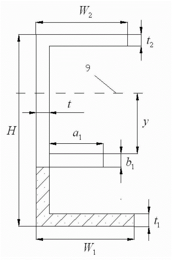
[0032] Known: H=300mm, W 1 =W 2 =50mm,t 1 = t 2 = 4.5mm, a 1 = 15mm, b 1 =4mm, t=3mmσ b =511 MPa. , K C = 2277 MPa mm .
[0033] Step 1. Determine the bending moment M of the integral spar:
[0034] M=σ 1 *s*H=180*50*4.5*300=1.215×10 7 Nmm;
[0035] Step 2. Assign an initial value A to the area of the arresting rib 1 =15*4, calculate the distance y=114.8mm from the neutral axis of the structural part of the non-shaded area of the overall spar to the crack arresting rib, and the flexural modulus I=4158122mm 4 ;
[0036] Step 3. Axial stress of crack arresting ribs
[0037] σ 2 = ...
PUM
 Abstract
Description
Claims
Application Information
 - R&D
- Intellectual Property
- Life Sciences
- Materials
- Tech Scout
- Unparalleled Data Quality
- Higher Quality Content
- 60% Fewer Hallucinations
Browse by: Latest US Patents, China's latest patents, Technical Efficacy Thesaurus, Application Domain, Technology Topic, Popular Technical Reports.
© 2025 PatSnap. All rights reserved.Legal|Privacy policy|Modern Slavery Act Transparency Statement|Sitemap|About US| Contact US: help@patsnap.com


