Electrode arrangement

An electrode device, electrode technology, applied in the direction of internal electrodes, head electrodes, electrotherapy, etc., to achieve the effect of high anti-interference degree

Inactive Publication Date: 2013-02-20
CERBOMED GMBH
View PDF13 Cites 8 Cited by
  • Summary
  • Abstract
  • Description
  • Claims
  • Application Information

AI Technical Summary

Problems solved by technology

[0009] It has been proven that the configuration of the electrodes described does not always lead to optimal treatment results

Method used


Image

  • Electrode arrangement
  • Electrode arrangement
  • Electrode arrangement

Examples


Embodiment Construction

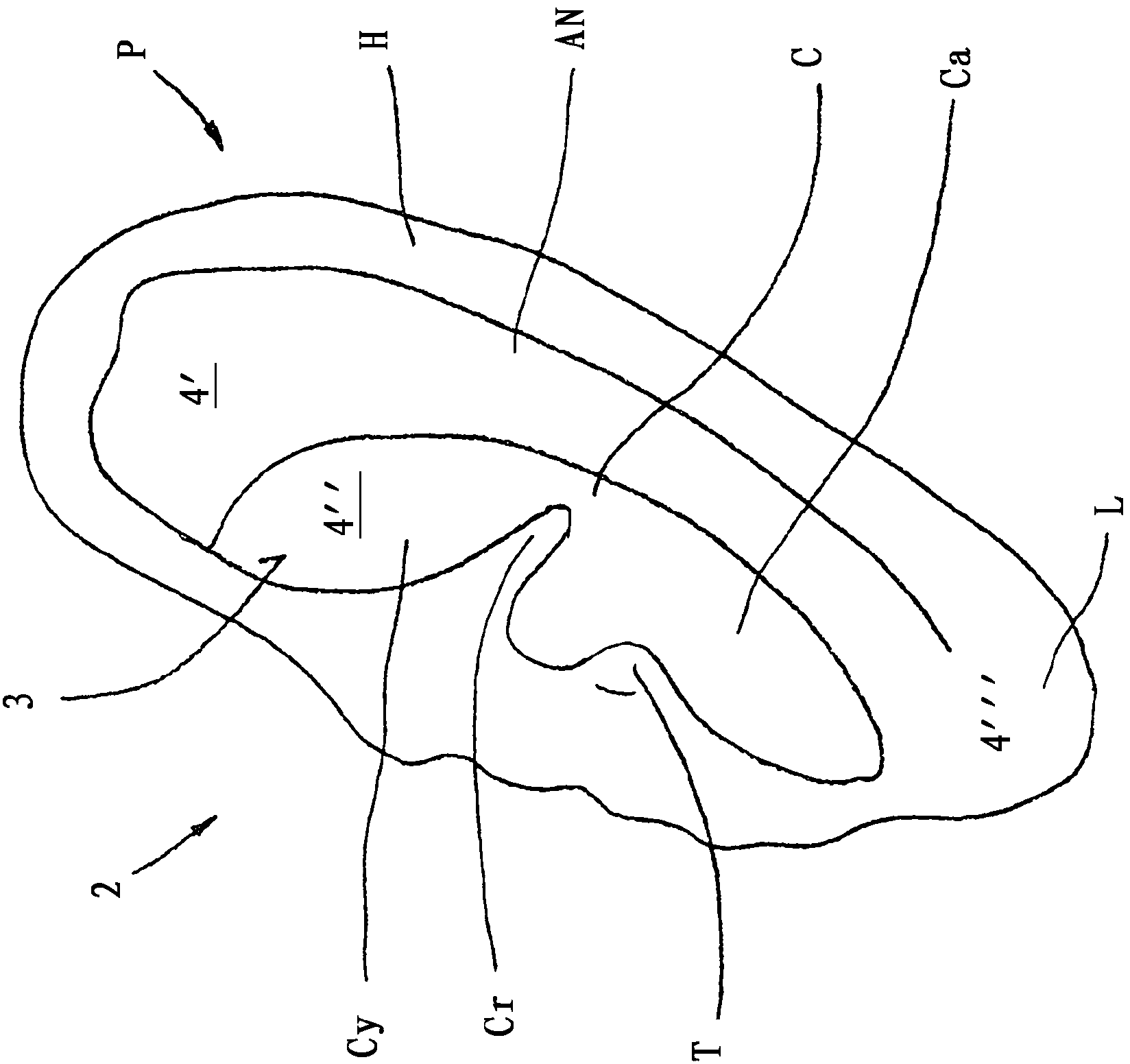
[0031] figure 1 A human (outer) ear 2 is sketched, the shape of which is defined by the Pinna (pinna) P. The pinna P comprises the helix H and the antihelix AN in a well-known manner; centrally placed is the concha C bordered by the tragus T. The earlobe L is located in the lower area. The concha C is divided into upper and lower regions, and the two regions are separated from each other by the crus Cr. The upper part of the outer ear C is the concha concha Cy, and the lower part is the concha cavity Ca.

[0032] Within the framework of the invention it can be seen that specific regions of the ear 2 are subjected to transcutaneous stimulation. The surface 3 of the ear 2 , here the inner side of the tragus T, is provided for the placement of the stimulating electrode acting as a cathode. Alternatively or additionally, a plurality of areas can be provided for the placement of the reference electrode acting as an anode, wherein the surface 4' of the upper area of ​​the helix ...


PUM


Abstract

The invention relates to an electrode arrangement (1) to be attached on and / or in the ear (2) of a human, wherein the electrode arrangement (1) is designed to exert a transcutaneous electric stimulation stimulus onto the surface (3, 4) of the ear (2) and wherein the electrode arrangement (1) has at least one stimulation electrode (5) and at least one reference electrode (6). In order to achieve improved transcutaneous stimulation of the vagus nerve in particular, the invention provides for the at least one stimulation electrode (5) to contact the surface (3) of the ear (2) via a first contact surface (A1) and for the at least one reference electrode (6) to contact the surface (4) of the ear (2) via a second contact surface (A2), wherein the second contact surface (A2) is at least three times the size of the first contact surface (A1).

Description

technical field [0001] The present invention relates to an electrode device mounted on and / or inside the human ear, wherein the electrode device is configured to perform percutaneous electrical stimulation on the surface of the ear, and wherein the electrode device has at least one stimulating electrode and at least one Reference electrode. Background technique [0002] It is generally known that invasive and non-invasive stimulation of nerves can have an influence on their neurophysiology and nerve electrical quality and thus on the function of the stimulated nerve. Different disease states can be treated in this way. There are many devices that can be used for both invasive and non-invasive stimulation. [0003] The present invention employs the method of transcutaneous electrical nerve stimulation. In this method, pulsed currents of different current forms, amplitudes, pulse durations and frequencies are applied across the skin to different nerves and their state param...

Claims


Application Information

Patent Timeline
IPC IPC(8): A61H39/00A61N1/36
CPCA61N1/0456A61N1/36032A61N1/36014A61N1/0526A61N1/0541A61H2205/027A61H39/002
Inventor J·埃尔里希
Owner CERBOMED GMBH
Why Eureka
Try Eureka