Resource allocation method and device for control channel information
A technology for controlling channels and control information, applied in wireless communication, electrical components, etc., to achieve the effect of dynamic change, enhanced scheduling flexibility, and increased blind detection space
- Summary
- Abstract
- Description
- Claims
- Application Information
AI Technical Summary
Problems solved by technology
Method used
Image


Examples
Embodiment 1
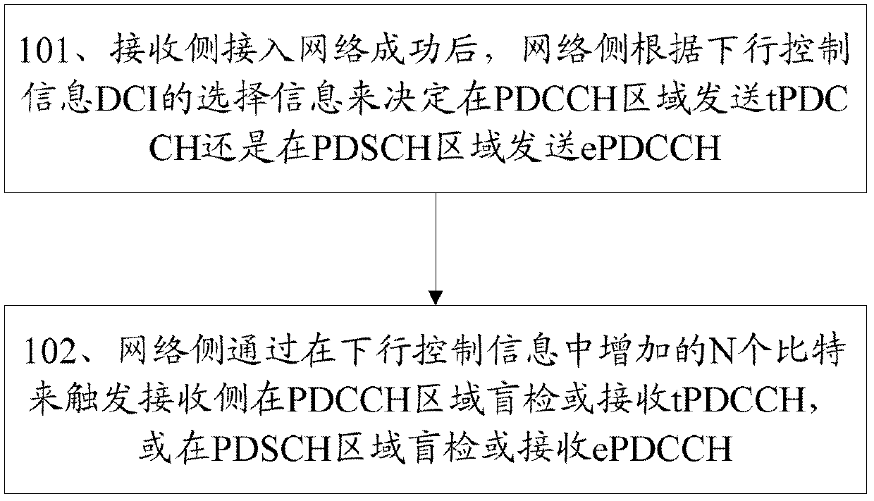
[0045] The network side adds N bits to the downlink control information DCI to trigger whether the receiving side needs to blindly detect tPDCCH in the PDCCH region or blindly detect ePDCCH in the PDSCH region in the next subframe. Specific methods such as figure 1 Shown:
[0046] Step 101: After the receiving side successfully accesses the network, the network side decides whether to send tPDCCH in the PDCCH region or send ePDCCH in the PDSCH region according to the selection information of the downlink control information DCI;
[0047] When the receiving side accesses the network, it obtains system broadcast scheduling information and the like in the PDCCH area. After the receiving side successfully accesses the network, the network side can decide to send DCI (tPDCCH) in the PDCCH area or send DCI in the PDSCH region according to the DCI selection information such as the environment of the receiving side, the channel condition of the receiving side, and the load of the sys...
Embodiment 2
[0051] The network side adds 1 bit to the downlink control information DCI to indicate whether the receiving side needs to blindly detect DCI in the PDCCH region or in the PDSCH region in the next subframe. When the receiving side accesses the network, consider obtaining system broadcast scheduling information in the PDCCH area. After the receiving side successfully accesses the network, the network side can decide to send DCI (tPDCCH) in the PDCCH area or send DCI in the PDSCH region according to the DCI selection information such as the environment of the receiving side, the channel condition of the receiving side, and the load of the system's downlink control channel. Regional transmission DCI (ePDCCH).
[0052] The network side may trigger ePDCCH transmission in subframes after the nth subframe in the nth subframe according to the DCI selection information. The receiving side performs blind detection in the nth subframe or receives the trigger information sent by the netw...
Embodiment 3
[0054] The network side triggers the receiving side to adopt ePDCCH blind detection or receive downlink control information by reusing the downlink control information DCI, such as DCI Format 1C.
[0055] When the receiving side accesses the network, consider obtaining system broadcast scheduling information in the PDCCH area. After the receiving side successfully accesses the network, the network side can decide to send DCI (tPDCCH) in the PDCCH area or send DCI in the PDSCH region according to the DCI selection information such as the environment of the receiving side, the channel condition of the receiving side, and the load of the system's downlink control channel. Regional transmission DCI (ePDCCH).
[0056] The network side may trigger ePDCCH transmission in subframes after the nth subframe in the nth subframe according to the DCI selection information. The receiving side performs blind detection in the nth subframe or receives the trigger information sent by the networ...
PUM
 Abstract
Description
Claims
Application Information
 - Generate Ideas
- Intellectual Property
- Life Sciences
- Materials
- Tech Scout
- Unparalleled Data Quality
- Higher Quality Content
- 60% Fewer Hallucinations
Browse by: Latest US Patents, China's latest patents, Technical Efficacy Thesaurus, Application Domain, Technology Topic, Popular Technical Reports.
© 2025 PatSnap. All rights reserved.Legal|Privacy policy|Modern Slavery Act Transparency Statement|Sitemap|About US| Contact US: help@patsnap.com