Illumination device

A technology of lighting device and installation area, which is applied in the directions of lighting device, fixed lighting device, lighting auxiliary device, etc., can solve the problem of difficult manufacturing cost of lighting device, and achieve the effect of low cost

Active Publication Date: 2013-02-13
SHARP KK
View PDF9 Cites 0 Cited by
  • Summary
  • Abstract
  • Description
  • Claims
  • Application Information

AI Technical Summary

Problems solved by technology

Therefore, there is a problem that it is difficult to reduce the manufacturing cost of the lighting device.

Method used


Image

  • Illumination device
  • Illumination device
  • Illumination device

Examples


Embodiment Construction

[0057] The following is based on Figure 1 to Figure 7 One embodiment of the present invention will be described.

[0058] (Structure of lighting device)

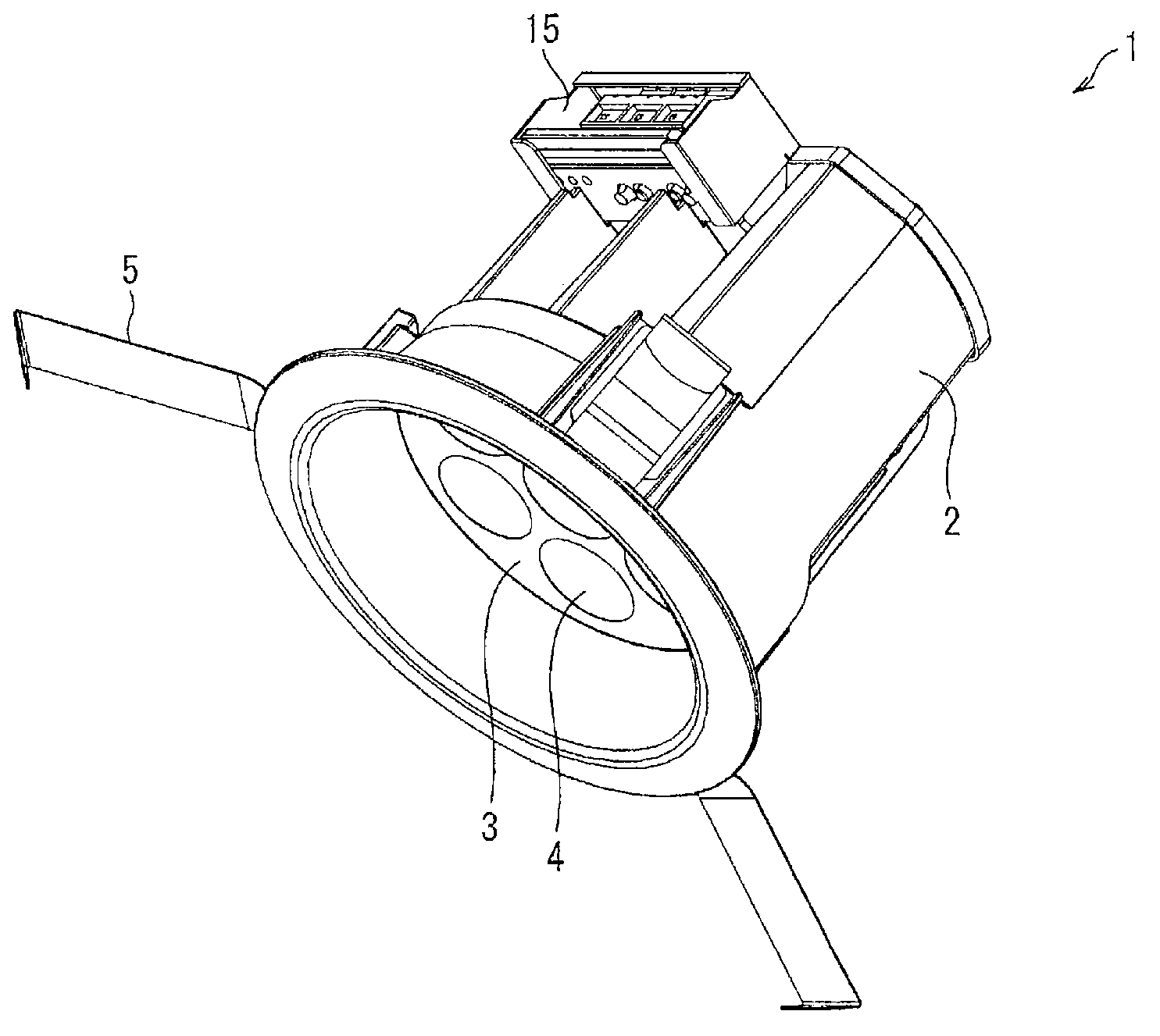
[0059] figure 1 It is a perspective view showing the lighting device 1 of this embodiment. The lighting device 1 is, for example, a lighting device used as a spotlight, and a transmission unit 3 is embedded in a cylindrical box 2 . A plurality of light emitting portions 4 for emitting light are formed on the transmission unit 3 . In addition, an installation spring 5 is provided at the edge of the annular opening of the box body 2 for installing the lighting device 1 on a ceiling or the like.

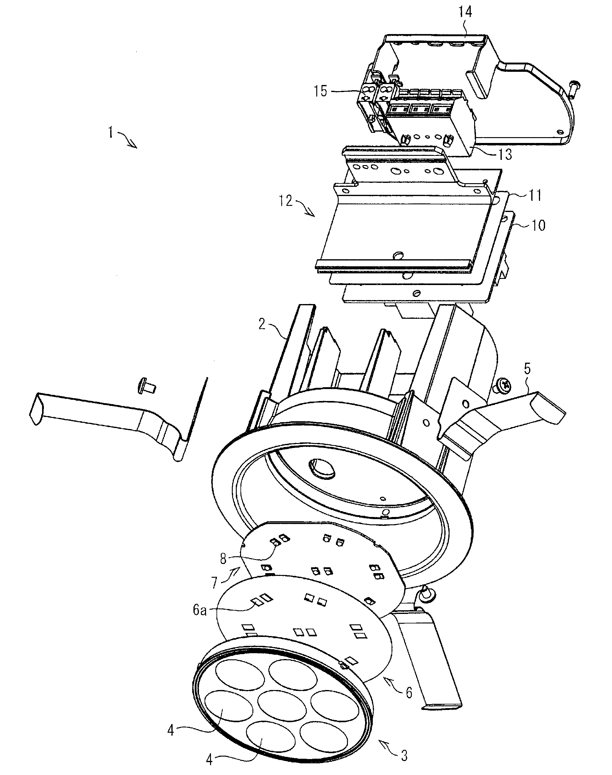
[0060] figure 2 It is an exploded perspective view of the lighting device 1 viewed from different angles. Such as figure 2 As shown, the lighting device 1 includes a box body 2, a transmission unit 3, a mounting spring 5, a reflector 6, an LED substrate 7, an LED (light source) 8, a circuit substrate 10, an insulating sheet 1...


PUM


Abstract

Disclosed is an illumination device (1) which can be manufactured at low cost in a plurality of types having different levels of brightness. The illumination device (1) is provided with a plurality of light-emitting sections (4) comprising LEDs (8a, 8b) for emitting light, and at least a part of the light-emitting sections (4) comprises a plurality of mounting areas (7a, 7b) in which the LEDs (8a, 8b) are mounted. It is possible to manufacture the illumination device in a plurality of types having different levels of brightness using identical transmission units (3), by selecting either one or two LEDs to be mounted in the light-emitting sections (4).

Description

technical field [0001] The present invention relates to lighting devices, in particular to lighting devices using LEDs as light sources. Background technique [0002] LEDs (Light Emitting Diodes) have the advantages of long life and low power consumption, so lighting devices using LEDs as light sources have been developed in recent years to replace incandescent and fluorescent lamps. [0003] Figure 8 (a) is a plan view of the conventional lighting device 101 viewed from the light emitting direction, Figure 8 (b) is a partial cross-sectional view of the lighting device 101 . Such as Figure 8 (a) with Figure 8 As shown in (b), the illuminating device 101 has seven light emitting parts 104 arranged in the closest cubic lattice on the emitting surface covered by the transmission unit 103 , and one LED 108 is installed inside each light emitting part 104 . [0004] Specific as Figure 8 As shown in (b), the light output unit 104 has one LED 108 , a reflective surface 1031 f...

Claims


Application Information

Patent Timeline
Patent Type & Authority Applications(China)
IPC IPC(8): F21V19/00F21V14/00F21S8/02F21Y101/02
CPCF21Y2105/001F21S8/026F21V7/0083F21V21/00F21Y2101/02F21V5/007F21Y2105/10F21Y2115/10
Inventor 山本裕之
Owner SHARP KK
Why Eureka
Try Eureka