Coupling device for connecting rotating body

A technology of rotating bodies and couplings, applied in the direction of couplings, elastic couplings, rigid shaft couplings, etc., can solve problems such as axial deviation, and achieve the effect of long-term aging resistance improvement and excellent stability

Active Publication Date: 2015-11-18
ADVICS CO LTD
View PDF9 Cites 0 Cited by
  • Summary
  • Abstract
  • Description
  • Claims
  • Application Information

AI Technical Summary

Problems solved by technology

However, when the rotating shaft on one side of the press-fit cover is, for example, the output shaft of a motor, a load generated by press-fitting is applied to the shaft, causing problems such as misalignment of components inside the motor in the axial direction.

Method used


Image

  • Coupling device for connecting rotating body
  • Coupling device for connecting rotating body
  • Coupling device for connecting rotating body

Examples


Embodiment Construction

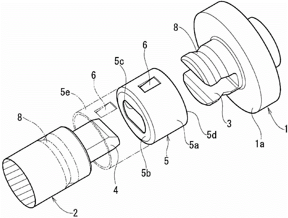
[0055] Below, combined with the accompanying drawings Figure 3 ~ Figure 18 Embodiments of the joint device for connecting rotating bodies of the present invention will be described.

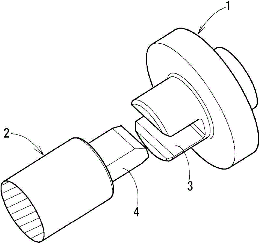
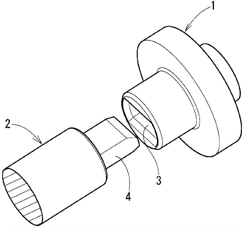
[0056] First of all, the basic mode of applying the shaft coupling device of the present invention is as follows: figure 1 as well as figure 2 shown. figure 1 It is a coupling device in which the sliding surface of the connecting part is opened on the outer periphery of the connecting part. figure 2 It is a joint device in which the sliding surface of the connecting part is not opened on the outer circumference of the connecting part. If the present invention is applied to figure 1 The open coupling device can be expected to get a particularly large effect, while in figure 2 It is also effective in non-open coupling devices.

[0057] These coupling devices are connected so that the first rotating body 1 and the second rotating body 2 face each other on the same axis and allow radial rel...


PUM


Abstract

A coupling device including a first rotary member and a second rotary member are opposed and connected to each other on the same axial line, wherein a cap to cover a connection part is a cylindrical shape having a bottom wall and a protrusion insertion hole formed on the bottom wall and covers the first rotary member from a connection end-side of the first rotary member, wherein the cap is axially urged by an elastic member to bring at least one of an opening-side end face and the bottom wall of the cap into contact with an annular end face formed on the first rotary member, and wherein an accommodation chamber of the connection part is formed in the cap to reserve lubricant, and an exit of the accommodation chamber of the connection part is blocked or narrowed by a force of the elastic member.

Description

technical field [0001] The present invention relates to a coupling device for connecting two rotating bodies by fitting and connecting two rotating bodies so as to be able to transmit torque. A coupling device that is effective when lubricating the mating surface of the joint to avoid slippage. Background technique [0002] There are many applications for connecting two rotating bodies with a coupling device having a shaft misalignment absorbing function. For example, it is used in brake hydraulic control devices for vehicles with control functions such as ABS (anti-lock brake control), ESC (anti-skid control), and TCS (driving force control system), and the device has a pump driven by a motor. [0003] Such pumps include a plunger pump and a gear pump. In the latter gear pump, an output shaft of a motor is connected to a rotor shaft to which a pump rotor is attached, and the motor is started to rotate the rotor shaft. [0004] The coupling between the rotor shaft and the ...

Claims


Application Information

Patent Timeline
Patent Type & Authority Patents(China)
IPC IPC(8): F16D3/04F16D3/84
CPCF16D1/101F16D1/10F16D1/116F16D3/841F16D2001/102F16D2300/06Y10T403/50Y10T403/608Y10T403/7045Y10T403/7098
Inventor 森广次前田淳一佐佐木泰博
Owner ADVICS CO LTD
Why Eureka
Try Eureka