Automatic blowing and pressing machine for electromagnetic valves

A solenoid valve and automatic technology, applied in metal processing, metal processing equipment, manufacturing tools, etc., can solve the problems of high production cost of solenoid valve, high labor cost, slow production efficiency, etc., and achieve low wage cost and small number of workers , the effect of high production efficiency

Active Publication Date: 2013-02-13
NINGBO AOKAI COMBUSTION GAS APPLIANCE
View PDF6 Cites 0 Cited by
  • Summary
  • Abstract
  • Description
  • Claims
  • Application Information

AI Technical Summary

Problems solved by technology

Therefore there is production efficiency slower in the assembling of prior art solenoid valve, needs more workman just to finish output, makes labor wage cost higher, and air gun is in working condition all the time, energy consumption is higher, finally makes the production cost of solenoid valve relatively high. high

Method used


Image

  • Automatic blowing and pressing machine for electromagnetic valves
  • Automatic blowing and pressing machine for electromagnetic valves

Examples


Embodiment Construction

[0016] The present invention will be further described below in conjunction with the accompanying drawings and specific embodiments.

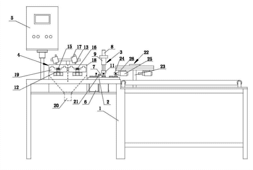
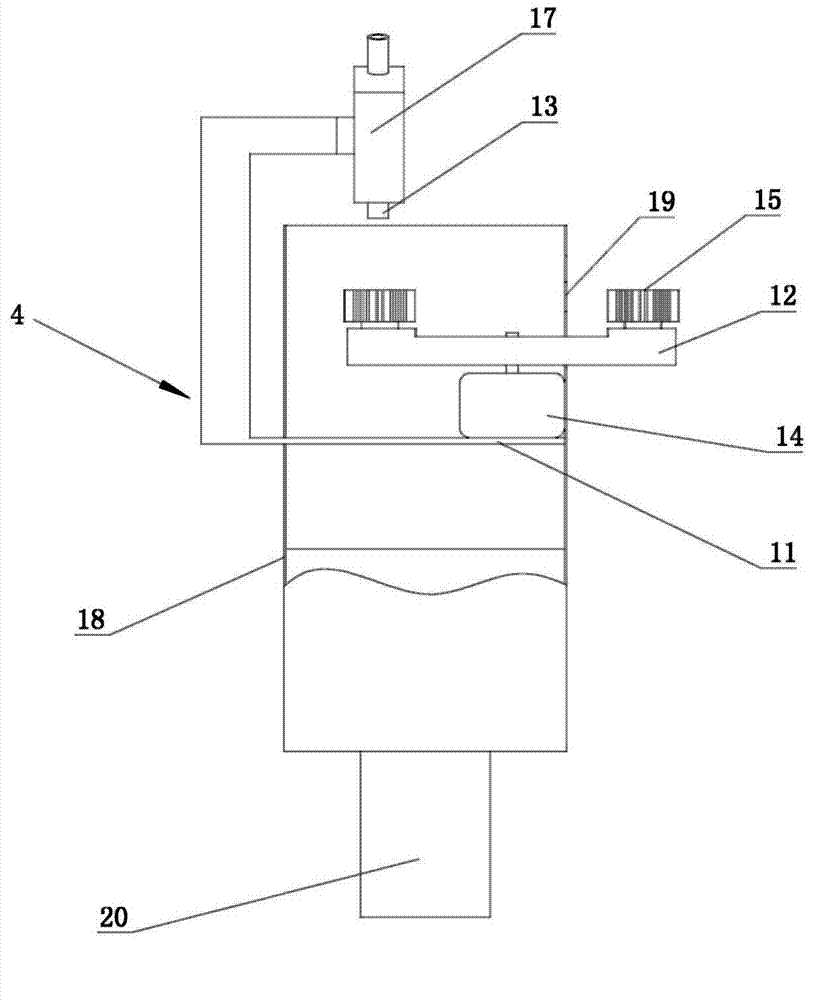
[0017] like figure 1 and figure 2 A solenoid valve automatic blowing machine is shown, which includes a base 1, a turntable 2, a pressing mechanism 3, an air blowing mechanism 4 and a control box 5, the base 1 is provided with an indexer 6, and the The turntable 2 is rotatably connected to the base 1, the rotating shaft of the indexer 6 is connected to the lower end surface of the turntable 2, and the axis of the rotating shaft of the indexer 6 is on the same line as the axis of the turntable 2, and the upper end surface of the turntable 2 is near the outer edge At least three solenoid valve clamps 7 (ten in this example, but also five, eight, nine, eleven or twelve, etc.) The clamps 7 are evenly distributed along the circumference of the turntable 2, and the center of the circle formed by the center of at least three solenoid valve clamps 7...


PUM


Abstract

The invention discloses an automatic blowing and pressing machine for electromagnetic valves, which comprises a base (1), a turntable (2), a laminating mechanism (3), a blowing mechanism (4) and a control box (5), wherein the base (1) is provided with a graduator (6), the turntable (2) is rotatablely connected to the base (1), a rotating shaft of the graduator (6) is connected with the lower end face of the turntable (2), the axis of the rotating shaft of the graduator (6) and the axis of the turntable (2) are in a same straight line, a position on the upper end face of the turntable (2) and close to the outer edge of the upper end face is circumferentially provided with at least three electromagnetic valve clamps (7), the at least three electromagnetic valve clamps (7) are uniformly distributed along the circumferential direction of the turntable (2), the circle center of a circumference formed by the centers of the at least three electromagnetic valve clamps (7) and the circle center of the turntable (2) are concentric, the laminating mechanism (3) is fixed in a position on the base (1) and close to the outer edge of the turntable (2), the control box (5) is fixed on the base (1), the blowing mechanism (4) is fixed in a position on the base (1) and close to the turntable (2), the blowing mechanism (4) and the laminating mechanism (3) are sequentially arranged along the rotating direction of the turntable (2), and the graduator (6), the blowing mechanism (4) and the laminating mechanism (3) are all electrically connected with the control box (5). Compared with the prior art, the automatic blowing and pressing machine disclosed by the invention has the characteristics of higher production efficiency, lower wages, relatively low energy consumption, and capability of enabling the production cost of electromagnetic valves to be lower.

Description

technical field [0001] The invention belongs to the field of automatic assembly equipment, in particular to a solenoid valve automatic blowing machine. Background technique [0002] At present, the assembly of solenoid valves in the prior art relies entirely on manual assembly by workers. During the operation, workers first hold the valve cover assembly in one hand and the valve seat assembly in the other, and then place them under their respective air guns for air blowing. After the completion, the worker manually pre-presses the valve cover assembly and the valve seat assembly, and finally places them on the fixture of the manual pressing machine. The worker moves the operating rod to press the valve cover assembly and the valve seat assembly. Therefore there is production efficiency slower in the assembling of prior art electromagnetic valve, needs more workman just to finish output, makes labor wage cost higher, and air gun is in working state all the time, energy consum...

Claims


Application Information

Patent Timeline
Patent Type & Authority Applications(China)
IPC IPC(8): B23P19/027
Inventor 葛华军蒋春飞项伟峰李倩
Owner NINGBO AOKAI COMBUSTION GAS APPLIANCE
Why Eureka
Try Eureka