
A burner system and a method for increasing the efficiency of a heat exchanger

一种热交换器、燃烧器的技术,应用在燃烧方法、燃烧器、气体燃料燃烧器等方向,能够解决不是控制爆燃脉冲等问题

Inactive Publication Date: 2013-02-06
M 策特纳
View PDF10 Cites 1 Cited by
  • Summary
  • Abstract
  • Description
  • Claims
  • Application Information

AI Technical Summary

Problems solved by technology

But these devices are not designed to completely block the wave front, and they are not devices that control the deflagration pulse

Method used


Image

  • A burner system and a method for increasing the efficiency of a heat exchanger
  • A burner system and a method for increasing the efficiency of a heat exchanger
  • A burner system and a method for increasing the efficiency of a heat exchanger

Examples


Embodiment Construction

[0062] The present invention relates to a method of burning, consuming or reacting compounds to achieve higher reaction temperatures between two or more compounds such as fuel and air. At the same time, the present invention relates to a method of increasing the efficiency of a heat exchanger or system connected to a burner or other device for heating water, steam or gaseous material with released thermal energy. The invention is primarily intended to improve heat exchangers for steam production, but also for other systems using heat exchangers associated with exothermic reactions to exchange thermal energy from one medium to another.

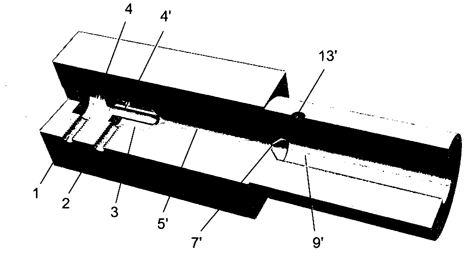
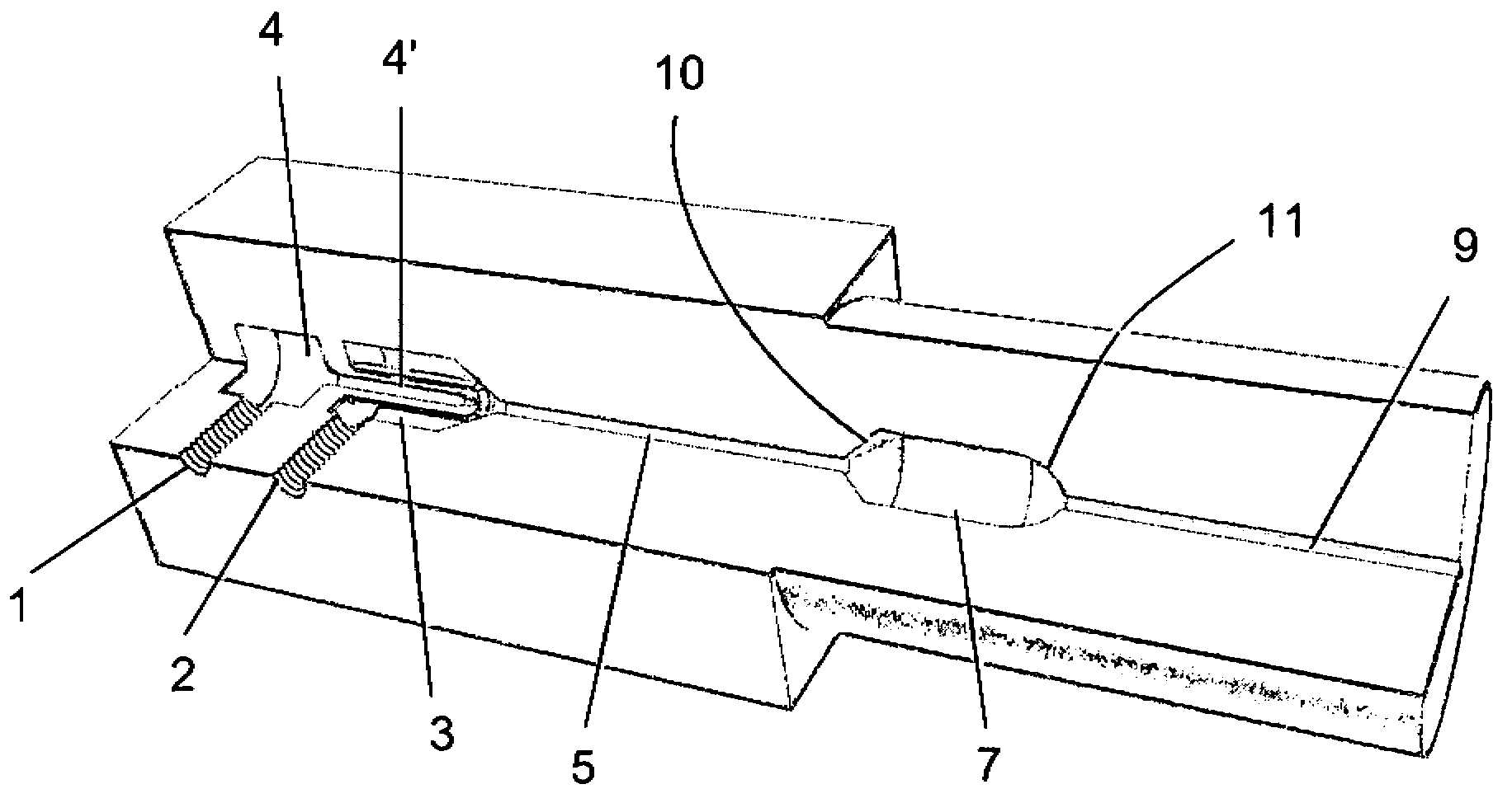
[0063] The present invention provides a burner system that produces pulsed pressure waves that can be easily used to increase the efficiency of heat exchangers by using controlled continuous pulsed explosions or deflagrations instead of continuous flow, which enables fluids to "heat" at extremely high temperatures. quasi-continuous combustion"....


PUM


Abstract

The present invention is a burner system that allows 'quasi continuous burning' of fluids at very high temperatures by using controlled continuous pulsing explosions or detonations instead of continuous flow and thus creating pulsing pressure waves that can be easily utilised for increasing heat exchanger efficiency. After initiation the explosions or detonations are maintained by use of infrared radiation. The pulsed explosions or detonations send their shock waves directly onto the heat exchanger walls thus introducing a bigger part of energy into the heat exchanger wall then would be possible with any other method of heat exchange. In addition the kinetic energy of the negative acceleration of the mass in the explosion or detonation wave is added as additional heat introduced into the heat exchanger walls.

Description

technical field [0001] The invention relates to the field of burner systems and heat exchangers. In particular, the present invention relates to new designs of burners capable of improving the transfer of thermal energy generated in exothermic reactions to heat exchangers for steam production or other uses of heat exchangers for exchanging thermal energy from one medium to another The heat transfer performance of the system. Background technique [0002] Reacting fuel and air or other compounds to produce free energy in the form of heat for a variety of purposes. This is usually achieved by means of the use of burners or combustion chambers as part of the combustion and heat exchangers for the resulting heat energy. As an example: In many power plants, fuel is burned and hot water or steam is produced from this thermal energy by means of heat exchangers. The entire system is often referred to as a "boiler". This steam is then used to drive turbines to produce electricity...

Claims


Application Information

Patent Timeline
Patent Type & Authority Applications(China)
IPC IPC(8): F23D14/12
CPCF23C15/00F23R7/00F23D14/126F23D14/46F23D14/18F23C3/002F23K5/007F23D14/02F23C2200/00F23C2205/00
Inventor M·策特纳
Owner M 策特纳
Learn More