Digital-to-analogue conversion method based on PWM (pulse width modulation) pin of DSP (digital signal processor)
A technology of digital-to-analog conversion and conversion method, which is applied in the direction of digital-to-analog converters, etc., and can solve problems such as bombing, problems, and increased costs
- Summary
- Abstract
- Description
- Claims
- Application Information
AI Technical Summary
Problems solved by technology
Method used
Image
Examples
Embodiment Construction
[0021] The present invention will be described in detail below in conjunction with the accompanying drawings and specific embodiments.
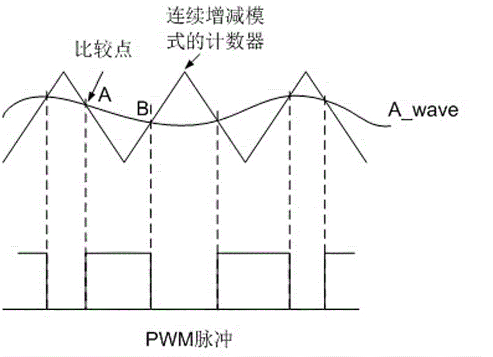
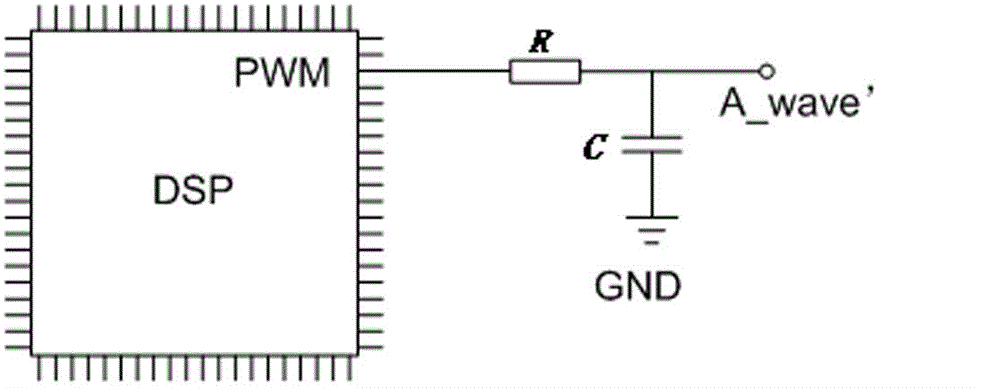
[0022] see Figure 1-3 , the present invention connects resistance R at PWM pin output inside DSP, connects a capacitance C between resistance R and circuit GND, and the common connection point of resistance R and capacitance C is output; Inside DSP, digital quantity A_wave is a time The quantity that has been discretized in terms of magnitude and amplitude, if the digital quantity corresponding to each time point is assigned to the comparison register inside the DSP, then the value in the counter (defined as the continuous increase and decrease counting mode) is equal to When the digital quantity of A_wave at this moment (this value is called the comparison match point), the specified PWM pin will output the corresponding level. see figure 1 It is stipulated that the output PWM pin is set to high level when the comparison matching point A ...
PUM
 Abstract
Description
Claims
Application Information
 - R&D Engineer
- R&D Manager
- IP Professional
- Industry Leading Data Capabilities
- Powerful AI technology
- Patent DNA Extraction
Browse by: Latest US Patents, China's latest patents, Technical Efficacy Thesaurus, Application Domain, Technology Topic, Popular Technical Reports.
© 2024 PatSnap. All rights reserved.Legal|Privacy policy|Modern Slavery Act Transparency Statement|Sitemap|About US| Contact US: help@patsnap.com


