
Supporting flow guide plate and separation filtering membrane column device

A technology of separation filtration and deflector plate, which is applied in the direction of semi-permeable membrane separation, membrane technology, chemical instruments and methods, etc., can solve the problems of reduced membrane column life, high energy consumption of system operation, and anti-pollution of membrane column, so as to reduce Effects of load intensity, improvement of product efficiency, and expansion of operating range

Inactive Publication Date: 2013-02-06
CHENGDU MEIFUTE MEMBRANE TECHNOLOGY CO LTD
View PDF6 Cites 36 Cited by
  • Summary
  • Abstract
  • Description
  • Claims
  • Application Information

AI Technical Summary

Problems solved by technology

Although the traditional spiral-wound membrane element has a high filling area density, the system application requires high water quality and complicated pretreatment conditions.
Because the organic pollutants, inorganic scaling substances and suspended particle impurities in the high-concentration fluid will easily block the mesh of the membrane column, resulting in frequent shutdown and cleaning of the system, which will reduce the life of the membrane column and even fail to operate normally.
[0003] The existing disc-type membrane column solves the above-mentioned anti-pollution problem of the membrane column
In fact, there is still a special problem with the disc-type membrane column, that is, the disc-type membrane column used for nanofiltration, ultrafiltration and microfiltration will cause a large amount of pressure loss due to multiple violent reverse flows of the fluid, and the energy consumption of the system will be large, resulting in its inability to heavily promote the app

Method used


Image

  • Supporting flow guide plate and separation filtering membrane column device
  • Supporting flow guide plate and separation filtering membrane column device
  • Supporting flow guide plate and separation filtering membrane column device

Examples


Embodiment 1

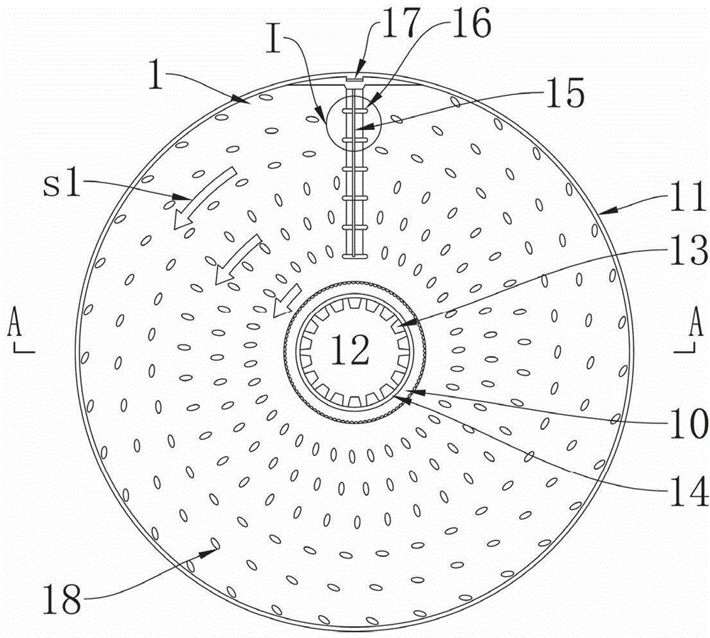
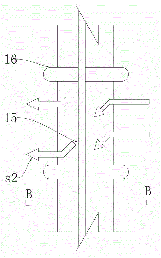
[0031] Embodiment 1: see Figure 1 to Figure 4 . figure 1 A supporting deflector is shown, and an outer rim 11 of a ring structure is provided on both sides of the supporting deflector 1 . The upper surface of the supporting deflector 1 is provided with an inner rim 14 of toroidal structure. The supporting deflector plate 1 is a disc with a central hole 12 concentric with the disc at its center.

[0032] Both sides of the disk are provided with six circles of flow-blocking bumps 18 , and each circle is evenly distributed with a plurality of flow-blocking bumps 18 . The anti-flow protruding point 18 semi-ellipsoid or the bottom surface of the anti-flow protruding point 18 is an ellipse, and the top is a protrusion with a smooth arc surface; The short diameter of the flow-blocking protruding point 18 on the edge of the disk coincides with the radius line of the disk. The flow blocking protrusions 18 surround the installation hole 12 and are concentrically dispersed. At the ...

Embodiment 2

[0038] Example 2: see Figure 5-Figure 10 . The separation and filtration membrane column device 3 described in this embodiment includes the supporting deflector plate 1 described in the embodiment. The separation and filtration membrane column device also includes a circular tube pressure-bearing shell 30 sealed by an upper end cover flange 39 , an upper fluid reverse disc 37 , a lower fluid reverse disc 36 , and a lower end cover flange 38 . The pressure-bearing shell 30 is equipped with an outer pull rod 43 for supporting and tightening the upper end cover flange 39 and the lower end cover flange 38 . The center of the upper end cover flange 39 , the upper fluid reverse disc 37 , the lower fluid reverse disc 36 and the lower end cover flange 38 is provided with a hole for the inner pull rod 31 to pass through. An inner tie rod 31 , an upper stacking plate 35 and a lower stacking plate 34 are installed in the pressure-bearing shell 30 for fastening and supporting the defle...


PUM

PropertyMeasurementUnit
Angleaaaaaaaaaa

Abstract

The invention discloses a supporting flow guide plate and a separation filtering membrane column device. The supporting flow guide plate is a disc with a central circular hole; a plurality of rings of flow blocking salient points are arranged on the disc; a radial rotational flow slit is also formed on the disc; one of two sides of the rotational flow slit of the disc upwarps to be extended into an upwarping part, and the other side is bent downwards to be extended into a lower bending part; and the upwarping part is parallel to the lower bending part. The separation filtering membrane column device comprises the supporting flow guide plate and a membrane; an inner pull rod for fixing the supporting flow guide plate and the membrane and upper and lower stacking plates are also installed in a bearing outer shell; a mounting hole is formed at the center of the membrane; a radial gap aligned with the rotational flow slit is also formed on the membrane; and an outer pull rod for supporting, tensioning and pressing upper and lower end cover flanges is installed outside the bearing outer shell. Compared with a traditional membrane component, the separation filtering membrane column device has the beneficial effects that the pressure loss is reduced by above 70 percent, and the product efficiency is improved. The separation filtering membrane column device is a special device with the advantages of antipollution and low energy consumption and is particularly suitable for an economical treatment process of a high-concentration fluid.

Description

technical field [0001] The invention belongs to the field of solid-liquid separation, and in particular relates to a filter device with a separation membrane as a medium. Background technique [0002] Membrane elements for fluid separation and filtration have similar properties and are prior art and widely patented. Although the traditional spiral-wound membrane element has a high filling area density, the system application has high requirements on the influent water quality and complicated pretreatment conditions. Because the organic pollutants, inorganic scaling substances and suspended particle impurities in the high-concentration fluid will easily block the screen of the membrane column, resulting in frequent shutdown and cleaning of the system, which will reduce the life of the membrane column and even fail to operate normally. [0003] The existing disc-type membrane column solves the above-mentioned anti-pollution problem of the membrane column. In fact, there is s...

Claims


Application Information

Patent Timeline
IPC IPC(8): B01D61/58
Inventor 宋岱峰韩亮许锦鹏
Owner CHENGDU MEIFUTE MEMBRANE TECHNOLOGY CO LTD
Learn More