
self-boosting brake

A self-energizing and brake technology, applied in the direction of brake type, axial brake, brake components, etc., can solve the problem of smooth brake release and achieve the effect of rapid braking

Active Publication Date: 2015-11-25
PINTSCH BUBENZER GMBH
View PDF10 Cites 0 Cited by
  • Summary
  • Abstract
  • Description
  • Claims
  • Application Information

AI Technical Summary

Problems solved by technology

But the brake cannot be released smoothly under load

Method used


Image

  • self-boosting brake
  • self-boosting brake
  • self-boosting brake

Examples


Embodiment approach

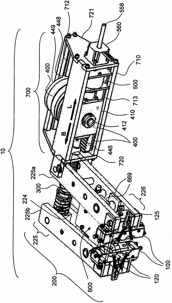
[0083] Figure 3b A schematic diagram showing a passive brake in the form of a lever brake. The brake is shown without a brake member 119 or brake disc 119 .

[0084] This brake also has two mutually symmetrical brake heads 100 opposite to each other (see figure 1 ), the brake head can bear against the brake disc 119 passing between the brake heads 100 on both sides with the working surface of the friction pad 116 using the lever set 200 . To this end, the brake lever 220 is rotated about a fixed lever center of rotation 221 , which in this embodiment is located at a fixed end 227 a or 227 b of the brake lever 220 , respectively. The brake head 100 passes through a structure (which is combined with the pin 222) figure 2 (similar to those described) are each rotatably centered on the brake lever 220 , so that here, too, the running surfaces of the friction pads 116 are always in contact with each other in the braking position, regardless of the inclination of the brake leve...


PUM


Abstract

A self-energizing braking device which, during braking, exerts a braking force on an active surface of a braking element (119), in particular a brake disc (119). The self-energizing braking device comprises a brake head (100) which can be adjusted between a braking position and a venting position and has a braking member (112) acting on the braking element (119) in the braking position. During braking, the braking member (112) moves over an adjustment distance along the active surface of the braking element (119) and is coupled to an adjustment component (113), which is adjustable with respect to the braking member (112) and perpendicularly with respect to the active surface, in such a manner that said adjustment component is adjusted counter to the action of a tensioning device (331) acting on the brake head (100). The adjustment component (113) thus builds up a braking force on the braking member (112) and therefore on the braking element (119). In this case, the adjustment distance of the adjustment component (113) can be set via a stop (115) acting on the braking member (112).

Description

technical field [0001] The invention relates to a self-boosting brake having a brake head with a brake body connected to an adjusting element, which acts on a brake element such as a brake disc or a brake drum during braking . As a result, a path occurs between the braking body and the adjusting part, and the stop acting on the braking body limits the movement of the adjusting part. The movement of the adjusting part is carried out against the action of a clamping mechanism, such as a spring, which thus exerts a defined constant braking force on the brake head and thus on the brake body. Background technique [0002] Industrial brakes are used in different work drive trains. They stop loads weighing tons or seconds and must work reliably. Industrial brakes have to meet many stringent requirements due to harsh environmental conditions and due to safety technology considerations. Depending on the field of application, these requirements vary considerably. As a rule, very ...

Claims


Application Information

Patent Timeline
Patent Type & Authority Patents(China)
IPC IPC(8): F16D65/14F16D55/224F16D55/226
CPCF16D55/2245F16D2065/386F16D2121/26F16D2125/24F16D2127/06F16D2127/10F16D2129/08
Inventor J·哈梅拉尔斯O·波尔藤J·米尔利切
Owner PINTSCH BUBENZER GMBH
Learn More