Eureka AIR delivers breakthrough ideas for toughest innovation challenges, trusted by R&D personnel around the world.

Electronic device

A technology for electronic devices and circuit boards, applied in the directions of light guides, optics, instruments, etc., can solve problems such as failure to work normally, weak luminous intensity of indicator lights, etc.

Inactive Publication Date: 2013-01-30
HONG FU JIN PRECISION IND (SHENZHEN) CO LTD +1
View PDF0 Cites 20 Cited by
  • Summary
  • Abstract
  • Description
  • Claims
  • Application Information

AI Technical Summary

Problems solved by technology

However, when the configuration of the internal electronic parts of the electronic device needs to change the installation position of the indicator light, the signal light emitted by the light source cannot completely irradiate the indicator light cover, so that the luminous intensity of the indicator light is very weak. thus not working properly

Method used


Image

  • Electronic device
  • Electronic device
  • Electronic device

Examples


Embodiment Construction

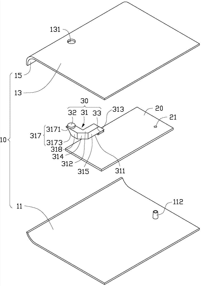
[0027] see figure 1 , in a preferred embodiment of the present invention, an electronic device includes a casing 10 , a circuit board 20 , and a light guide structure 30 . The light guide structure 30 is installed on the circuit board 20 and is installed in the casing 10 together with the circuit board 20 .

[0028] The casing 10 includes a bottom wall 11 , a top wall 13 , and a side wall 15 connected between the bottom wall 11 and the top wall 13 . The bottom wall 11 defines a positioning post 112 for fixing the circuit board 20 . The top wall 13 defines a through hole 131 . The circuit board 20 defines a positioning hole 21 corresponding to the positioning column 112 . In one embodiment, the bottom wall 11 is substantially parallel to the top wall 13; the side wall 15 is arc-shaped.

[0029] The light guiding structure 30 includes a light guiding column 31 , an indicator light cover 32 , and a light source 33 . In one embodiment, the indicator light cover 32 is a circle...


PUM

PropertyMeasurementUnit
Acute angleaaaaaaaaaa

Abstract

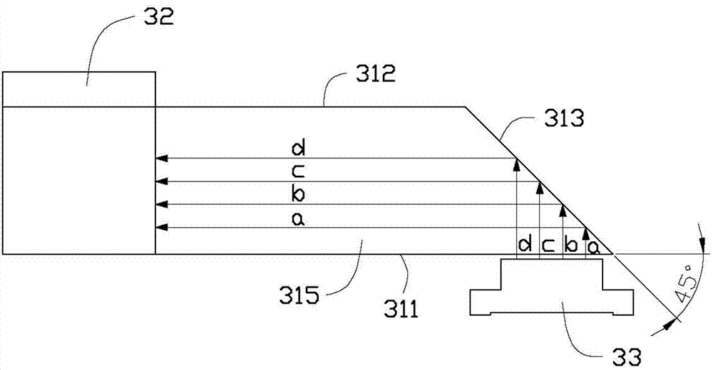
An electronic device comprises a casing and a light guiding structure. The casing comprises a bottom wall and a top wall which is approximately parallel to the bottom wall, and a circuit board is mounted on the bottom wall. The light guiding structure comprises a light source, an indicator lamp cap and a light guide column between the light source and the indicator lamp cap, the light source is electrically connected with the circuit board and used for generating plurality of parallel light rays which are perpendicular to a plane of the circuit board, the indicator lamp cap is mounted on the top wall, a line between the indicator lamp cap and the light source forms an acute angle with the plane of the circuit board, the light guide column comprises at least one reflection surface, and the parallel light rays can be emitted into the indicator lamp cap after being reflected at least for one time by the at least one reflection surface.

Description

technical field [0001] The invention relates to an electronic device, especially an electronic device with a light guiding structure. Background technique [0002] Generally, indicator lights are widely used in daily life to indicate relevant lighting, light signals, technical status of working systems, and to send out alarm light signals for abnormal conditions, etc. For example, in common electronic devices, such as the indicator lights in 3C products are installed on the outside of a panel, a light source is installed on a PCB board in the electronic device, and the light source and indicator lights are usually arranged in a direction roughly perpendicular to the PCB board. On the same straight line, like this, the signal light that light source sends just can directly irradiate on the indicator light cover of indicator light. However, when the configuration of the internal electronic parts of the electronic device needs to change the installation position of the indicat...

Claims


Application Information

Patent Timeline
IPC IPC(8): H05K5/02F21V8/00
Inventor 黄富国
Owner HONG FU JIN PRECISION IND (SHENZHEN) CO LTD
Why Eureka
Eureka Blog
Learn More