
mobile terminal

A technology for mobile terminals and outgoing terminals, applied in the field of mobile terminals, can solve the problems of large bonding area and difficulty in rework, and achieve the effect of reducing bonding area and increasing detachability

Active Publication Date: 2015-07-29
HUAQIN TECH CO LTD
View PDF4 Cites 0 Cited by
  • Summary
  • Abstract
  • Description
  • Claims
  • Application Information

AI Technical Summary

Problems solved by technology

[0003] The technical problem to be solved by the present invention is to overcome the defect that the touch screen of the mobile terminal in the prior art is too large and difficult to remove for rework, and to provide a mobile terminal

Method used


Image

  • mobile terminal
  • mobile terminal
  • mobile terminal

Examples


Embodiment Construction

[0016] The preferred embodiments are given below, and the present invention will be described more clearly and completely in conjunction with the accompanying drawings.

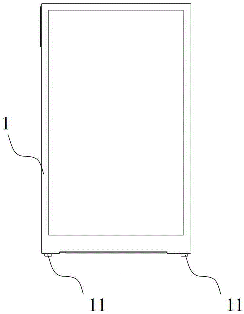
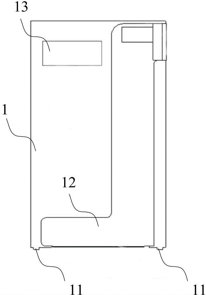
[0017] Such as figure 1 and figure 2 As shown, the touch screen 1 in this embodiment is provided with two bosses 11, and the bosses 11 are located at the same end of the FPC (flexible circuit board) outlet end 12, and the area 13 is a bonding area, so that the area 13 is separated from the FPC outlet end. Open, so as to avoid bonding to the FPC outlet.

[0018] For the convenience of plugging, in this embodiment, the bosses 11 are symmetrically distributed on both sides of the FPC outlet 12 .

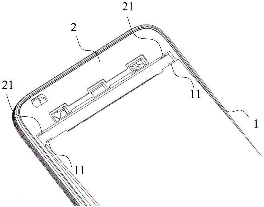
[0019] When installing, first as image 3 As shown, insert the boss 11 into the slot 21 of the corresponding housing 2, and then Figure 4 As shown, the other end of the touch screen 1 is bonded to the casing 2 .

[0020] The touch screen 1 in this embodiment adopts a capacitive touch screen with a size of 4.0 in...


PUM


Abstract

The invention discloses a mobile terminal, which comprises a shell and a touch screen, wherein at least one boss for inserting the shell is arranged at one end of the touch screen; and the other end of the touch screen is stuck to the shell. By the mobile terminal, under the condition that the touch screen is not lifted, the sticking area is reduced, and the detachability of the touch screen is improved.

Description

technical field [0001] The present invention relates to a mobile terminal. Background technique [0002] Most of the current mobile terminals have touch screens, and most of the touch screens adopt the design mode of front-mounted screens. During installation, the back of the touch screen is glued to the casing. Since the bonding area of ​​the back glue on both sides of the touch screen is small, it is easy to produce unbalanced force on the display screen and cause the touch screen to warp. At present, the main way to ensure the force balance of the display screen is to use large-area adhesive bonding, but compared with the disadvantages caused by the warping of the touch screen, it is often a last resort. Although the problem of the warping of the touch screen is avoided, due to the large bonding area , It is not easy to remove after installation, resulting in a scrap rate of more than 90% of products that need to be reversed, which greatly increases the cost of products ...

Claims


Application Information

Patent Timeline
Patent Type & Authority Patents(China)
IPC IPC(8): H04M1/02
Inventor 李志勇孙博
Owner HUAQIN TECH CO LTD
Learn More