Eureka AIR delivers breakthrough ideas for toughest innovation challenges, trusted by R&D personnel around the world.

Motor control method

A motor control and motor technology, applied in the control system, motor control, AC motor control, etc., can solve the problems of large installation space, increased installation space, installation cost and circuit design complexity, and the inability to reduce the error rate of motor operation

Active Publication Date: 2013-01-30
SUNONWEALTH ELECTRIC MACHINE IND
View PDF5 Cites 7 Cited by
  • Summary
  • Abstract
  • Description
  • Claims
  • Application Information

AI Technical Summary

Problems solved by technology

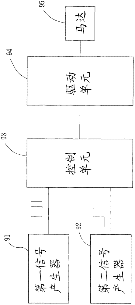
Wherein, if the steering signal and the rotational speed signal cannot be correctly transmitted to the control unit 93 at the same time due to factors such as circuit failure or transmission distortion (for example: the rotational speed signal or the rotational speed signal is distorted, etc.), the control unit 93 The control signal cannot be generated correctly, so that the motor 95 cannot rotate forward or reverse at the control speed correctly
Therefore, existing motor control methods cannot reduce the error rate of motor operation
[0008] Since the existing motor control method needs to use the rotational speed signal and the steering signal at the same time, two signal generators are required, namely the first signal generator 91 and the second signal generator 92, which increases the installation space and installation cost. and circuit design complexity
Therefore, the existing motor control method needs to occupy a large installation space, and will increase the installation cost and circuit design complexity

Method used


Image

  • Motor control method
  • Motor control method
  • Motor control method

Examples


Embodiment Construction

[0080] In order to make the above-mentioned and other objects, features and advantages of the present invention more comprehensible, the preferred embodiments of the present invention are specifically cited below, together with the accompanying drawings, as follows:

[0081] The "Pulse Width Modulation" (Pulse Width Modulation, PWM) described in the present invention refers to that each cycle of the pulse wave signal contains a logic "1" and a logic "0", which is used to power on and off electronic products , where the time ratio of the logic "1" to a single cycle is the duty cycle (Duty Cycle), the reciprocal of the time of a single cycle is the frequency (Frequency), and the voltage value of the logic "1" is the amplitude (Amplitude) , It can be understood by ordinary knowledge in the technical field to which the present invention belongs.

[0082] The "running" in the present invention refers to the process of the motor rotating when the motor is powered on, which can be un...


PUM


Abstract

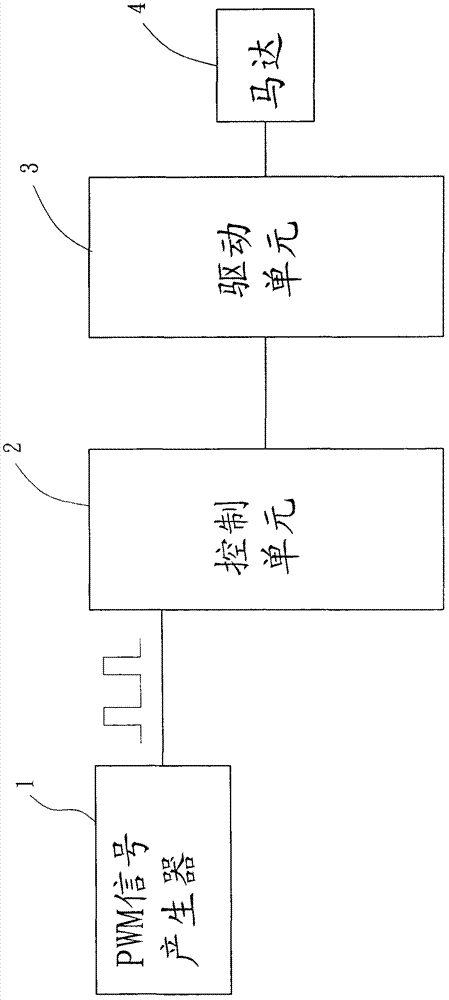
A motor control method comprises: inputting a PWM signal into a control unit for the control unit to obtain a direction command and a speed command by an identification rule, and generating a control signal according to the direction and speed commands by the control unit; and generating a driving signal according to the control signal by the driving unit for driving a motor to operate according to the direction and speed commands.

Description

technical field [0001] The present invention relates to a motor control method, in particular to a motor control method capable of simultaneously controlling the rotation speed and the steering direction of the motor by only relying on a single signal. Background technique [0002] In order to effectively dissipate the heat generated by the electronic products during operation, the fan blades are usually driven by a motor to rotate in a predetermined direction to generate airflow, so that the electronic products can achieve the purpose of heat dissipation. However, when the external airflow is introduced into the electronic product, it is easy to cause dust accumulation inside the electronic product. Therefore, at the beginning of starting the electronic product, the motor is usually controlled to rotate in the opposite direction to the predetermined rotation direction for a period of time (for example: 5 seconds), so as to perform the dust removal operation on the electroni...

Claims


Application Information

Patent Timeline
Patent Type & Authority Applications(China)
IPC IPC(8): H02P29/00
CPCH02P29/00H02P23/0068H02P23/0072H02P23/22H02P23/24
Inventor 陈同安李杰峯简登山林文杰
Owner SUNONWEALTH ELECTRIC MACHINE IND
Why Eureka
Eureka Blog
Learn More