Equipment and method for measuring slope error of optical lens

A slope error and optical lens technology, which is applied in the field of aberration detection of transmission lenses, can solve the problems of cumbersome measurement and long time, and achieve the effect of simple implementation, low cost and good accuracy

Inactive Publication Date: 2013-01-30
DALIAN GREAT OCEAN NEW ENERGY DEV
View PDF7 Cites 7 Cited by
  • Summary
  • Abstract
  • Description
  • Claims
  • Application Information

AI Technical Summary

Problems solved by technology

This method is cumbersome to measure, takes a long time, and because the slope obtained is the slope of an area, not the slope of each point, it will cause relatively large errors

Method used


Image

  • Equipment and method for measuring slope error of optical lens
  • Equipment and method for measuring slope error of optical lens
  • Equipment and method for measuring slope error of optical lens

Examples


Embodiment Construction

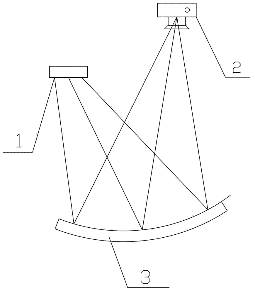
[0027] The present invention provides a device and method for measuring the slope error of an optical lens. The technical scheme of the present invention will be described in detail below with reference to the accompanying drawings.

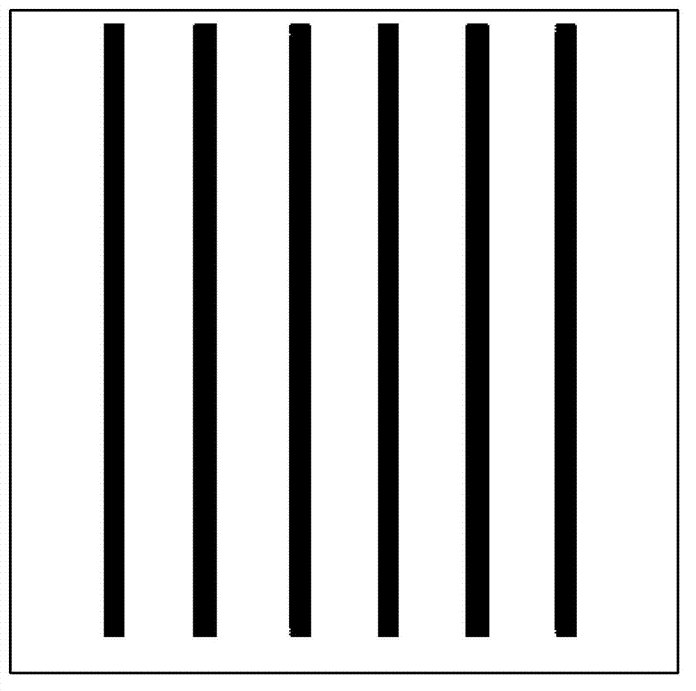
[0028] The device for measuring the slope error of an optical lens of the present invention includes an image target made according to the standard lens surface type of the inspected lens; an image collector, the acquisition lens faces the inspected lens curved surface, and is used to collect the image target formed by the inspected lens curved surface Imaging images and sending the collected imaging images to the image processor; the image processor is used to compare and analyze the imaging image and the theoretical image of the target, calculate the offset of each image point of the imaging image, and convert the offset Is the displacement, and the slope error of each image point is obtained according to the displacement. The image target is a re...


PUM


Abstract

The invention discloses equipment for measuring slope error of an optical lens. The equipment comprises an image target, an image acquisition device and an image processor, wherein the image target is manufactured according to the type of a standard lens curved surface of a detected lens; an acquisition camera lens faces towards the curved surface of the detected lens for acquiring an image formed by the image target through the curved surface of the detected lens and transmitting the acquired image to the image processor; and the image processor is used for performing contrastive analysis on the image and an image target theoretical image, calculating offset of each image point of the image, converting the offset into displacement and obtaining the slope error of each image point according to the displacement. The invention also provides a method for measuring the slope error of the optical lens. By implementing the technical scheme provided by the invention, the equipment and the method have the beneficial effects of capability of obtaining the slope error by comparing the image formed by the image target through the detected lens with the image target theoretical image, easiness in implementation, low cost and capability of keeping good accuracy.

Description

Technical field [0001] The invention belongs to the field of optical lens detection, and can be used for detecting the slope error of ordinary reflective lenses and special surface reflective lenses, and can also be used for aberration detection of transmission lenses. Background technique [0002] In the current field of solar thermal power generation, since the reflection and concentration of the lens are involved, there are certain requirements for the surface flatness of the reflecting lens. When the quality of the lens surface is poor, adverse effects such as distortion of the reflected light spot and uneven light intensity will occur, and the main lens parameter that causes this effect is the slope error of the lens. For a point on the lens, the slope error refers to the error between the theoretical direction and the actual direction of the light reflected by the point under normal incident conditions, which is an angle value. In order to avoid this situation, it is usual...

Claims


Application Information

Patent Timeline
Patent Type & Authority Applications(China)
IPC IPC(8): G01B11/26G01M11/02
Inventor 郭右利王振声周改改
Owner DALIAN GREAT OCEAN NEW ENERGY DEV
Why Eureka
Try Eureka