
Pump device

A technology of pump device and pump chamber, which is applied in the direction of pump device, pump, and parts of pumping device for elastic fluid, etc., can solve problems such as weakening effect, and achieve the effect of reducing damage

Active Publication Date: 2013-01-30
SANKYO SEIKI MFG CO LTD
View PDF7 Cites 7 Cited by
  • Summary
  • Abstract
  • Description
  • Claims
  • Application Information

AI Technical Summary

Problems solved by technology

[0006] In a pump device in which the pump casing is composed of two members, there is a problem that when the two members are stacked to divide the pump chamber, if the O-ring arranged between the two casings is damaged, the The effect of preventing liquid leakage from the pump chamber is reduced

Method used


Image

  • Pump device
  • Pump device
  • Pump device

Examples


other Embodiment approach

[0110]In the above example, the front end surface 97a of the anti-rotation protrusion 97 is at the same position as the annular lower end surface 94 of the annular protruding portion 91 in the axis L direction, but it may be located at a lower position than the annular lower end surface 94 in the axis L direction. The lower end face 94 is closer to the side of the lower shell 11 . In this case, the anti-rotation protrusion 97 can be inserted into the anti-rotation recess 69 before the annular protruding portion 91 of the upper case 12 is inserted into the annular step portion 68 of the lower case 11. Relative rotation of the upper case 12 and the lower case 11 is prevented. In addition, if the dimension in the axial direction is sufficient, the front end surface 97a of the anti-rotation protrusion 97 may be formed to be located on the side of the upper case 12 than the annular lower end surface 94 of the annular protrusion 91 in the direction of the axis L. Location. That is...


PUM


Abstract

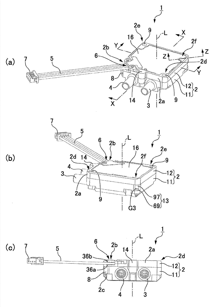
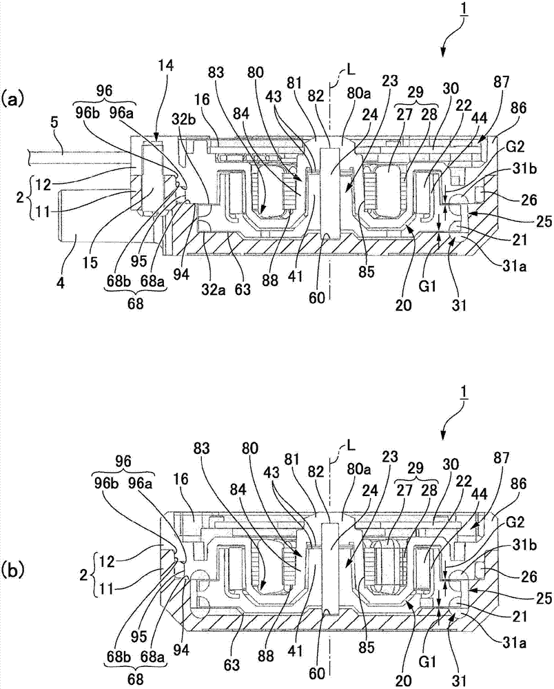
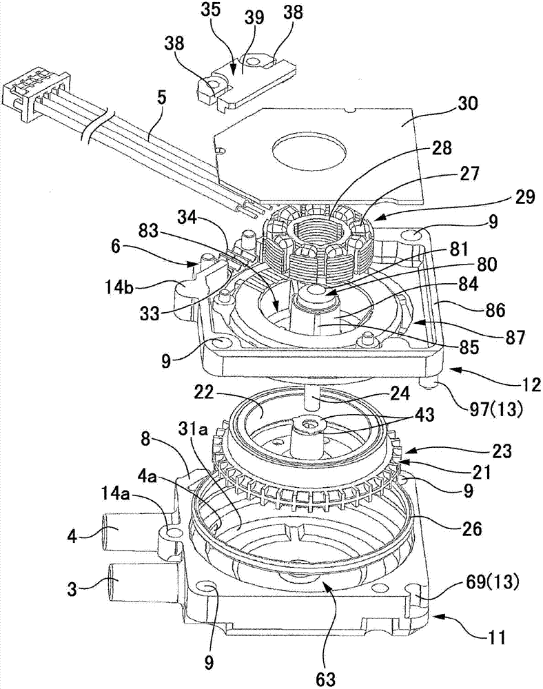
A pump device (1) may include a first case (12) provided with a circular ring-shaped protruded part (91), a second case (11) provided with a circular ring-shaped stepped part (68) into which the circular ring-shaped protruded part (91) is coaxially inserted, an O-ring (26) which is mounted on a circular outer peripheral face (95) of the circular ring-shaped protruded part and is crushed between the circular outer peripheral face of the circular ring-shaped protruded part and a circular inner peripheral face of the circular ring-shaped stepped part in a direction perpendicular to an axial line (L) of the circular ring-shaped protruded part, and a turning prevention mechanism (97) which prevents the first case(12) and the second case (11) from being relatively turned to each other around the axial line when the circular ring-shaped protruded part (91) of the first case (12) is inserted into the circular ring-shaped stepped part (68)of the second case (11) to form the pump chamber (25). As a result, the O-ring (26) is not twisted under a crushed condition, so the O-ring (26) is not damaged.

Description

technical field [0001] The present invention relates to a pump device in which the pump casing is composed of two laminated casings. Background technique [0002] Patent Document 1 describes a pump device for pressurizing a liquid, and a pump casing including a pump chamber inside the pump device is constituted by a lid and a bottom that are stacked up and down. In the pump device of the above-mentioned document, an O-ring is arranged between the cover and the bottom, and the O-ring is pressurized by tightening the screw for fixing the cover and the bottom. Prevent fluid leakage from the pump chamber. [0003] prior art literature [0004] Patent Literature [0005] Patent Document 1: Japanese Patent Laid-Open No. 2009-156242 [0006] In the pump device in which the pump casing is composed of two members, when the two members are stacked to divide the pump chamber, if the O-ring arranged between the two casings is damaged, the problem is that the O-ring disposed between ...

Claims


Application Information

Patent Timeline
Patent Type & Authority Applications(China)
IPC IPC(8): F04D5/00F04D29/40
CPCF04D5/006F04D29/40F04D13/0673F04D5/00F04D29/4286F04D29/42F04D29/426F04D29/086F04D13/0626
Inventor 横沢满雄田中彰吾
Owner SANKYO SEIKI MFG CO LTD
Learn More