
Time difference measurement-based antenna switching type radio frequency positioning method

A technology for antenna switching and positioning methods, which is applied in wireless communication, cooperative devices, instruments, etc., and can solve the problems of expensive receiving antenna arrays, large direction measurement errors, and high deployment costs

Active Publication Date: 2013-01-23
BEIJING YIMAI MEDICAL TECH CO LTD
View PDF3 Cites 18 Cited by
  • Summary
  • Abstract
  • Description
  • Claims
  • Application Information

AI Technical Summary

Problems solved by technology

This method has high positioning accuracy, but the cost of system deployment is high due to the need for expensive receiving antenna arrays
In the case of many indoor obstacles and non-line-of-sight effects, the direction measurement error is large

Method used


Image

  • Time difference measurement-based antenna switching type radio frequency positioning method
  • Time difference measurement-based antenna switching type radio frequency positioning method
  • Time difference measurement-based antenna switching type radio frequency positioning method

Examples


Embodiment Construction

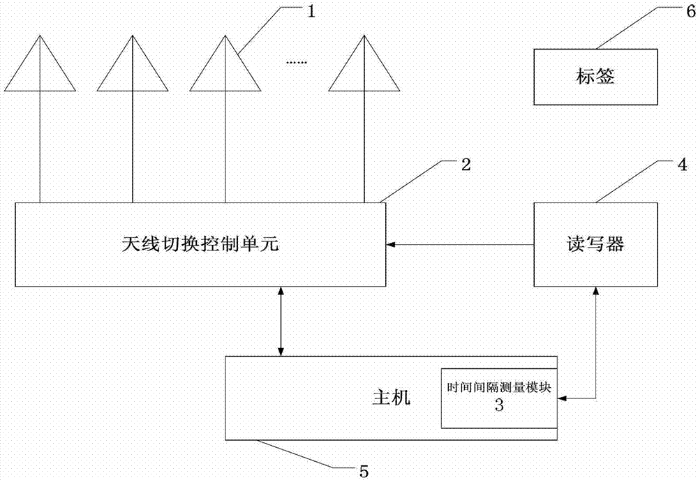
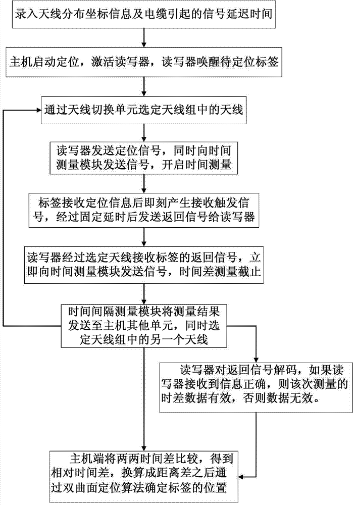
[0041] The present invention completes the positioning of the tag by switching different positioning antennas and measuring the time interval from when the signal is sent from the reader to when the returned information of the tag is received by the reader. The measured data is processed and calculated at the host to obtain the position information of the tag.

[0042] The technical scheme adopted in order to achieve the above-mentioned purpose is:

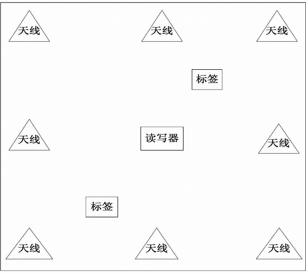
[0043] Such as figure 1 As shown, multiple positioning antennas in the antenna group at the reader-writer end are distributed in space. The number of positioning antennas depends on the actual application environment and accuracy requirements. Increasing the number of positioning antennas can improve to a certain extent. Positioning accuracy, but the number and arrangement of positioning antennas must ensure that no matter where the tag is located within the measurement range, it can be covered by at least four positioning antenna...


PUM


Abstract

The invention discloses a time difference measurement-based antenna switching type radio frequency positioning method and belongs to the technical field of radio frequency positioning. The method is characterized by comprising the following steps of: distributing positioning antennae of an antenna group in space in which the position of a reader serves as a coordinate origin, and recording the coordinate information of each positioning antenna into a host; switching and accessing different positioning antennae through an antenna switching control unit, and measuring the time interval from the moment when the reader sends a signal to the moment when the reader receives the information which is returned by a label; processing the measured data through the host to acquire the time difference of transmitting electromagnetic waves in the space when different positioning antennae are accessed, and then acquire the distance difference when the label reaches corresponding two different antennae according to the time difference, and then setting up a plurality of hyperboloid equations; and performing iterative computation on a plurality of hyperboloid equations to acquire the position coordinate of the label.

Description

technical field [0001] The invention belongs to the technical field of RFID, in particular to a radio frequency positioning method based on time interval measurement technology. Background technique [0002] Radio Frequency Identification (RFID) uses electromagnetic waves or magnetic field coupling to transmit data, so its most important feature is non-contact identification. Compared with other contact automatic identification technologies, radio frequency identification technology has many advantages, such as long recognition distance, high reading rate, large storage space, various shapes, reusable and so on. [0003] A typical radio frequency identification system is mainly composed of three parts: the host, the reader and the radio frequency tag. The host realizes the control of the reader-writer and the exchange and processing of data through the digital interface, and provides effective information for the user. The reader is a device for accessing tag data, and is ...

Claims


Application Information

Patent Timeline
IPC IPC(8): H04W24/08H04W64/00G06K17/00
Inventor 张春彭琪李佐昭王志华
Owner BEIJING YIMAI MEDICAL TECH CO LTD
Learn More