
Automatic implementation method for high-uniformity magnet shim coil design

A shimming coil and uniformity technology, applied in the direction of measuring magnetic variables, measuring devices, instruments, etc., can solve problems such as difficult winding, irregular coil shape, and unrealizable design schemes

Active Publication Date: 2015-04-08
INST OF MODERN PHYSICS CHINESE ACADEMY OF SCI
View PDF5 Cites 0 Cited by
  • Summary
  • Abstract
  • Description
  • Claims
  • Application Information

AI Technical Summary

Problems solved by technology

[0003] So far, there is no complete method for automatic design of magnet shim coils
Moreover, the existing active shimming designs are all calculated by traditional analytical methods or compiled by professionals with special calculation programs.
Due to the use of origin approximation conditions in the analytical method calculation process, the obtained coil design is not optimal, it is difficult to obtain a more satisfactory field uniformity, and due to the limitation of the length of the actual coil bobbin, the design scheme cannot be realized at all; Programs, such as C language, Matlab software, etc., due to the single algorithm, such as genetic algorithm, hybrid algorithm, reverse boundary element method, etc., consume a lot of memory and take a long time, the shape of the obtained coil is very irregular, and it is not easy to wind Realization, and the program requires professional personnel to operate and maintain, it is difficult for ordinary personnel to intervene

Method used


Image

  • Automatic implementation method for high-uniformity magnet shim coil design
  • Automatic implementation method for high-uniformity magnet shim coil design
  • Automatic implementation method for high-uniformity magnet shim coil design

Examples


Embodiment Construction

[0018] The preferred embodiments of the present invention will be described below in conjunction with the accompanying drawings. It should be understood that the preferred embodiments described here are only used to illustrate and explain the present invention, and are not intended to limit the present invention.

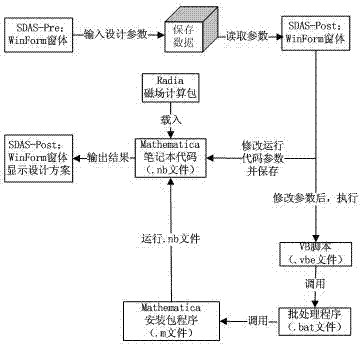
[0019] An automatic implementation method for the design of high-uniformity magnet shim coils, comprising the following steps:

[0020] (1) Use the nuclear magnetic resonance probe to measure the magnetic field intensity distribution within the field area, and use the least square method to fit the first 10 order components of the magnetic field according to the spherical harmonic function, and obtain the intensity values ​​of each order shimming quantity;

[0021] (2) In the data interface, input the strength value of the above shimming amount and the operating current density value required for shimming, the length of the shimming area, the diameter of the shimming...


PUM


Abstract

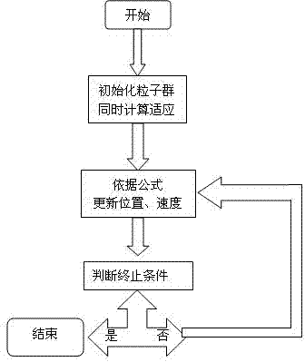
The invention discloses an automatic implementation method for a high-uniformity magnet shim coil design. The method comprises the following steps of: measuring the magnetic field intensity distribution within a region range by utilizing a nuclear magnetic resonance probe, and fitting the first 10-order components of the magnetic field expanded according to spherical harmonics by utilizing a least square method so as to obtain the intensity value of the shimming quantity of each order; inputting a shimming intensity numerical value, selecting an algorithm, and then storing the shimming intensity numerical value and the algorithm; assigning the stored numerical value and algorithm to a shimming code module; loading a Radia three-dimensional electromagnetic field calculation packet into the shimming code module and carrying out optimal computation on the optimization model; optimizing the calculation result, calculating shim coil shape parameters, a coil three-dimensional structural drawing and an error iteration path by virtue of a linear programming method or a particle swarm optimization based on an analytical method; and manufacturing a shim coil according to the calculated specific coil shape parameters and coil three-dimensional topological structure. The method disclosed by the invention can be used for achieving the purposes of simplicity in operation and high precision.

Description

technical field [0001] The invention relates to the field of magnetic field processing, in particular to an automatic realization method for the design of high-uniformity magnet shim coils. Background technique [0002] At present, magnets with a high uniformity magnetic field on the order of 0.1 ppm are mainly used in magnetic resonance imaging equipment, ion traps and other devices. The designed main magnet can generally achieve a field uniformity of 1000ppm. To further improve the uniformity, a special shimming method is required. Commonly used shimming methods include passive shimming and active shimming. Passive shimming uses soft magnetic iron sheets. Due to the influence of the minimum thickness of iron sheets and temperature changes, it is difficult to further improve the uniformity. Active shimming generally uses the coils corresponding to the orthogonal spherical harmonic components of each order to generate a magnetic field to offset the inhomogeneity. Since the...

Claims


Application Information

Patent Timeline
Patent Type & Authority Patents(China)
IPC IPC(8): G01R33/3875
Inventor 杜俊杰吴巍袁平马力祯
Owner INST OF MODERN PHYSICS CHINESE ACADEMY OF SCI
Learn More