
Floating foundation of offshore wind-driven generator

A wind turbine and floating technology, applied in wind turbine components, wind engines, wind power generation, etc., can solve the problems of fragile floating foundation, easy collision, poor stability of a single floating foundation, etc., and reach the height of the center of gravity Low, efficiency-enhancing, light-weight effects

Active Publication Date: 2013-01-09
SOUTH CHINA UNIV OF TECH
View PDF3 Cites 21 Cited by
  • Summary
  • Abstract
  • Description
  • Claims
  • Application Information

AI Technical Summary

Problems solved by technology

However, the stability of the single floating foundation of this patent is poor, and each unit is connected by elastic thin cables, which is prone to collisions, resulting in easy damage to the floating foundation

Method used


Image

  • Floating foundation of offshore wind-driven generator
  • Floating foundation of offshore wind-driven generator
  • Floating foundation of offshore wind-driven generator

Examples


Embodiment 1

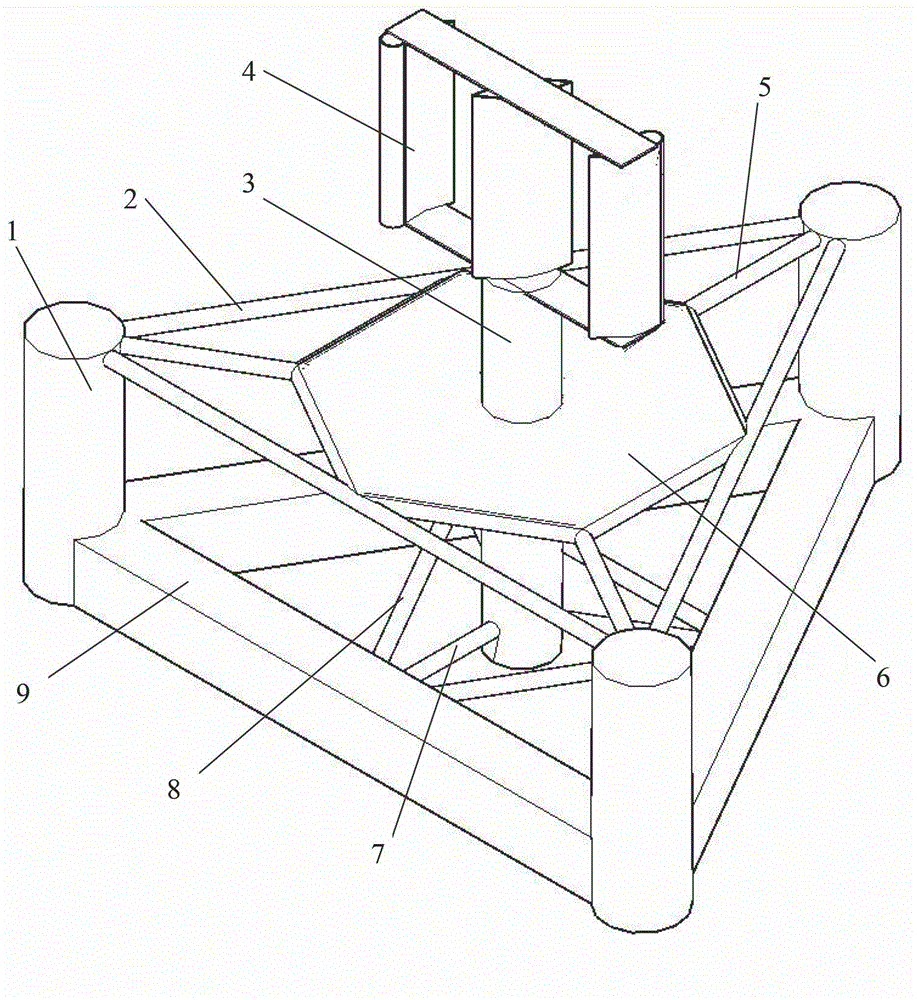
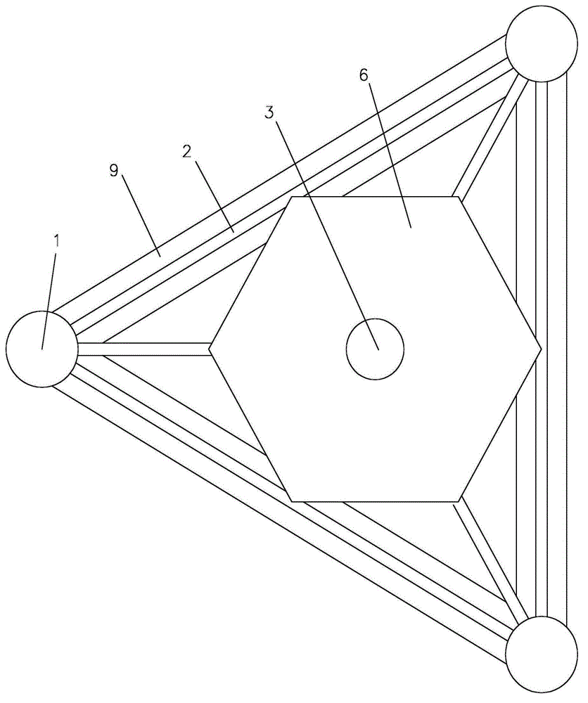
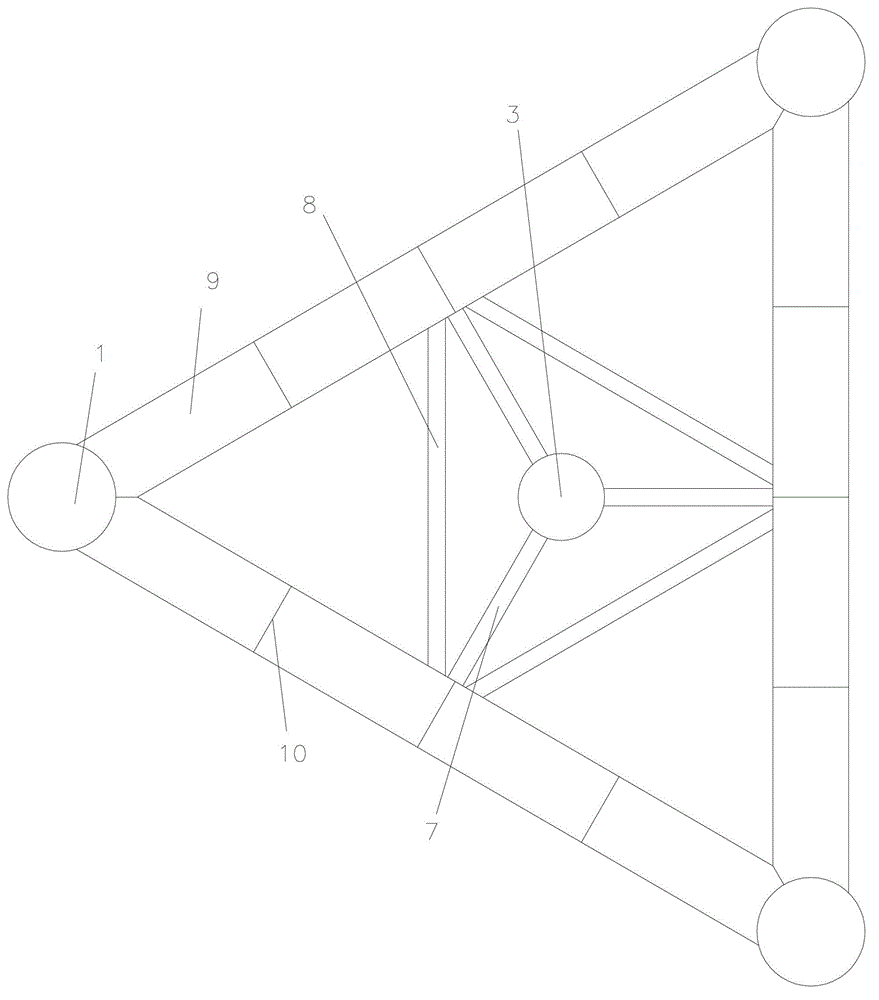
[0037] like figure 1 and figure 2 The floating foundation of an offshore wind power generator includes at least one floating foundation unit 17, the floating foundation unit 17 includes a tower 3 and a wind generator 4, and the wind generator 4 is installed on the top of the tower 3 The upper end also includes a plurality of buoys 1, connecting rods 2, square braces 9, first support rods 5 and second support rods 7, the plurality of buoys 1 are evenly distributed on the periphery of the tower column 3, and the lower ends of the adjacent buoys 3 The upper end of the buoy 1 is fixedly connected with the middle part of the tower column 3 through the first support rod 5, and the square support 9 fixed at the lower end of the buoy 1 is connected with the tower through the second support rod 7. The lower end of the column 3 is fixedly connected; the square brace 9 is located below the water surface of the seawater, and the lower end of the buoy 1 is fixedly connected with the seab...

Embodiment 2

[0049] like Figure 10 , the floating foundation of the offshore wind power generator further includes a tension cable 21, the floating foundation group is fixedly connected to the seabed through the tension cable 21, and the lower end of the buoy 1 is fixedly connected to the seabed through the tension cable 21.


PUM


Abstract

The invention discloses a floating foundation of an offshore wind-driven generator, comprising at least one floating foundation unit; the floating foundation unit comprises a tower column, a wind-driven generator, a plurality of float bowls, a connecting rod, a square support, a first supporting rod and a second supporting rod; the wind-driven generator is arranged at the upper end of the tower column; the plurality of float bowls are uniformly distributed at the periphery of the tower column, the lower ends of the adjacent float bowls are fixedly connected through the square support, and the upper ends of the adjacent float bowls are fixedly connected through the connecting rod; the upper ends of the float bowls are fixedly connected with the middle part of the tower column through the first supporting rod, and the square support fixed at the lower ends of the float bowls is fixedly connected with the lower end of the tower column through the second supporting rod; and the square support is located below the surface of seawater, and the lower ends of the float blows are fixedly connected with the seabed. The floating foundation disclosed by the invention is favorable in stability and capable of adjusting the position of the center of the gravity and the resonant frequency of the wind-driven generator and reducing the unbalance degree of bulk movement of the floating foundation in waves. Changed power combination is realized through a plurality of floating foundations so that different power utilization requirements are met.

Description

technical field [0001] The invention relates to offshore wind power generation equipment, in particular to a floating foundation for an offshore wind power generator. Background technique [0002] As a clean and renewable energy, wind energy has been paid more and more attention by countries all over the world. Currently, most wind power projects are on land. With the development of wind power technology, offshore wind power has gradually become a new field of wind power development. Because offshore wind resources are abundant and will not be restricted by land use. Because the wind resources at sea are much better than those on land, and the wind resources in far sea areas are better than those in shallow sea areas in the coastal zone, it is an inevitable direction for wind power to go to the far sea. The current offshore wind power projects are mostly located in offshore areas, using fixed foundations. Floating foundations are an inevitable choice for the development ...

Claims


Application Information

Patent Timeline
IPC IPC(8): F03D11/00E02D27/44
CPCY02E10/722
Inventor 陈超核
Owner SOUTH CHINA UNIV OF TECH
Learn More