
High-pressure discharge lamp

A technology for high-pressure discharge lamps and discharge capacitors, which is applied in the direction of discharge lamps, gas discharge lamps, and parts of gas discharge lamps, and can solve problems such as short circuits and failure to realize the combination of auxiliary dischargers.

Inactive Publication Date: 2013-01-02
OSRAM GMBH
View PDF4 Cites 1 Cited by
  • Summary
  • Abstract
  • Description
  • Claims
  • Application Information

AI Technical Summary

Problems solved by technology

[0003] The one-piece ignition aid has the disadvantage that the ignition aid cannot be combined with an auxiliary arrester serving as an additional ignition aid in the outer bulb of the high-pressure discharge lamp because the ignition aid For this auxiliary discharger is an electrical short circuit along the discharge vessel
The symmetrical embodiment of the one-piece ignition aid has the further disadvantage that the electric field is distributed symmetrically between the ignition aid and the two electrodes due to its capacitive coupling to the two electrodes, so that at each Only half of the field strength above an electrode is usable
On the other hand, the asymmetric embodiment of the one-piece ignition aid layer according to the prior art has the further disadvantage that the efficiency of the ignition aid layer depends on the polarity of the half-wave of the ignition voltage pulse and on the Which of the two electrodes is charged with the "hot" potential of the ignition voltage pulse, i.e. with a high potential compared to ground potential

Method used


Image

  • High-pressure discharge lamp
  • High-pressure discharge lamp
  • High-pressure discharge lamp

Examples


Embodiment Construction

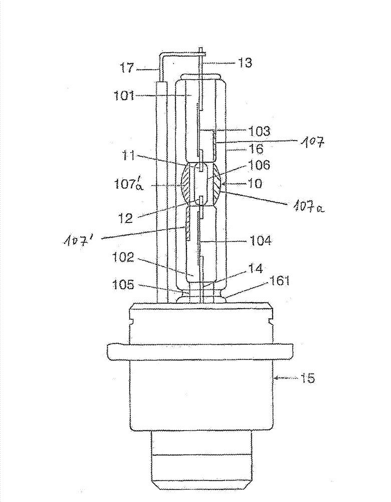
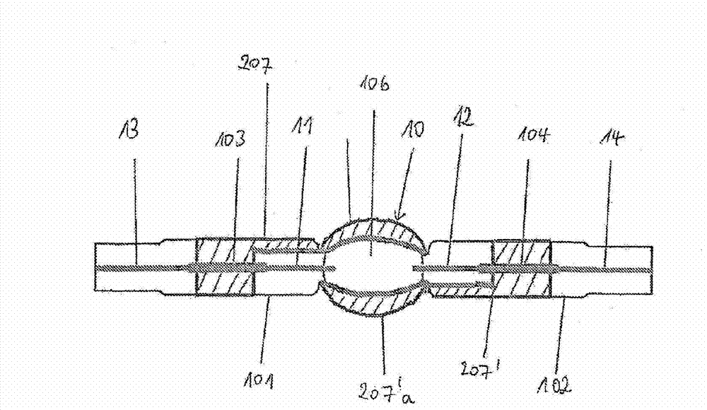
[0020] of the present invention figure 1 A first embodiment schematically shown in is a mercury-free halogen metal vapor high-pressure discharge lamp with an electrical power consumption of approximately 35 watts. The lamp is intended for use in a motor vehicle headlight. The lamp has a volume of 24mm 3 A discharge vessel 10 of quartz glass, sealed on both sides, in which is hermetically enclosed an ionizable filling made of xenon gas and halides of the metals sodium, scandium, zinc and indium composition. In the region of discharge space 106 , the inner contour of discharge vessel 10 is cylindrical and its outer contour is elliptical. The discharge space 106 has an inner diameter of 2.6 mm and an outer diameter of 6.3 mm. The two ends 101 , 102 of the discharge vessel 10 are each sealed by means of a molybdenum foil fusion 103 , 104 . Two electrodes 11 , 12 protrude into discharge space 106 of discharge vessel 10 , between which electrodes a discharge arc responsible for...


PUM


Abstract

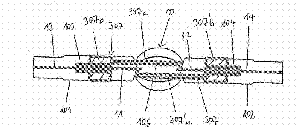
The invention relates to a high-pressure discharge lamp having an ignition assisting layer (107, 107') disposed on the discharge vessel (10). According to the invention, the electrically conductive ignition assisting layer (107, 107') is made of at least one first layer segment (107) and one second layer segment (107'), wherein the first layer segment (107) is disposed on a first sealing end (101) of the discharge vessel (10) and extends to the surface of the area of the discharge vessel (10) enclosing the discharge chamber (106), and a wherein the second layer segment (107') is disposed on the second sealing end (102) of the discharge vessel (10) and extends to the surface of the area of the discharge vessel (10) enclosing the discharge chamber (106), so that the parts (107a, 107'a) of the first and second layer segments (107, 107'); disposed on the surface of the area of the discharge vessel (10) enclosing the discharge chamber (106) are disposed spaced apart from each other and the layer segments (107, 107') are galvanically separated.

Description

technical field [0001] The invention relates to a high-pressure discharge lamp according to the preamble of claim 1 . Background technique [0002] Such a high-pressure discharge lamp is known, for example, from EP 1 632 985 A1. Said reference describes a high-pressure discharge lamp for automotive headlamps having a light-transmissive discharge vessel which surrounds a discharge space and has two sealed ends; and has two An electrode into the discharge space and a filling arranged in the discharge space for generating a gas discharge, and a power feed leading out of the sealed end for supplying the electrodes. An electrically conductive layer serving as an ignition aid is arranged on the surface of the discharge vessel. The ignition aid layer is formed in one piece. The ignition aid layer extends over the entire longitudinal extent of the discharge space and, according to a symmetrical embodiment, over both sealed ends of the discharge vessel and, according to an asymmet...

Claims


Application Information

Patent Timeline
Patent Type & Authority Applications(China)
IPC IPC(8): H01J61/35H01J61/54
CPCH01J61/35H01J61/54H01J61/547H01J61/125H01J61/366H01J61/827
Inventor 迈克尔·伯尼克马克·齐希
Owner OSRAM GMBH
Learn More