Glass melting furnace and method for melting glass
A glass melting furnace and glass technology, applied in glass furnace equipment, glass production, glass manufacturing equipment, etc., can solve the problem of increased discharge
- Summary
- Abstract
- Description
- Claims
- Application Information
AI Technical Summary
Problems solved by technology
Method used
Image

Examples
no. 1 approach
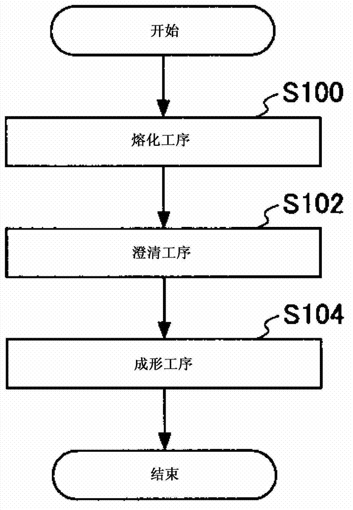
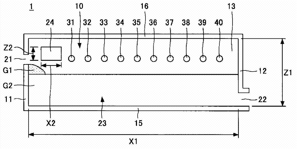
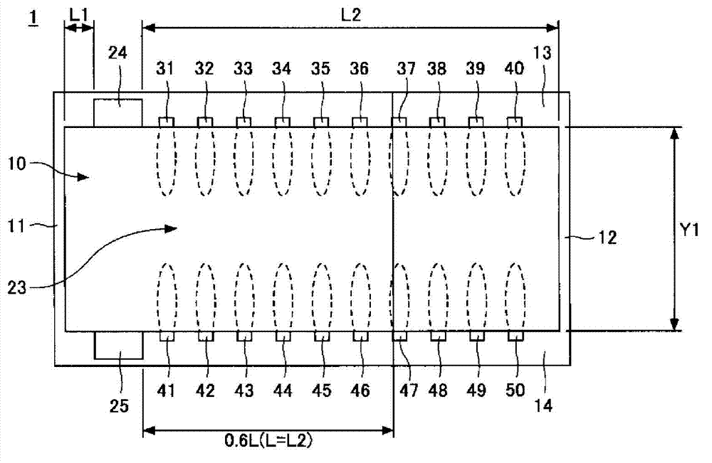
[0037] figure 1 It is a process drawing of the manufacturing method of the glassware in embodiment of this invention. figure 2 It is a side view of the internal structure of the glass melting furnace in 1st Embodiment. image 3 It is a top view of the internal structure of the glass melting furnace in 1st Embodiment. image 3 In , the combustion area of each burner (the outer edge of the flame of each burner) is shown surrounded by a dotted line.
[0038] Such as figure 1 As shown, the manufacturing method of a glass product includes: a melting step (S100) of melting a glass raw material to obtain a molten glass; A forming step of a predetermined shape (S104).
[0039] Among the above-mentioned processes, the clarification process (S102) is a process of supplying the molten glass obtained in the melting process to a clarification tank, floating and removing air bubbles in the molten glass. As a method of promoting the floating of air bubbles, there are, for example, a ...
no. 2 approach
[0078] The second embodiment relates to the glass melting furnace of the present invention. Specifically, the glass melting furnace of the present invention has a configuration in which a pair of exhaust ports are arranged at the center in the front-rear direction of the side wall. That is, the glass melting furnace of the present invention has a configuration in which a pair of exhaust ports are arranged in the center between the front wall and the rear wall.
[0079] Figure 4 It is a side view of the internal structure of the glass melting furnace in 2nd Embodiment. Figure 5 It is a plan view of the internal structure of the glass melting furnace in 2nd Embodiment. Figure 5 In , the outer edge of the flame of each burner is surrounded by a dotted line. It should be noted, Figure 4 , Figure 5 in, right with figure 2 , image 3 The same components are given the same reference numerals and descriptions thereof are omitted.
[0080] Such as Figure 4 , Figure 5 ...
no. 3 approach
[0092] The third embodiment relates to the glass melting furnace of the present invention. Specifically, the glass melting furnace of the present invention has a configuration in which a plurality of burners are arranged in a zigzag shape with a flow path interposed therebetween.
[0093] Figure 6 It is a side view of the internal structure of the glass melting furnace in 3rd Embodiment. Figure 7 It is a top view of the internal structure of the glass melting furnace in 3rd Embodiment. Figure 7 In , the outer edge of the flame of each burner is surrounded by a dotted line. It should be noted, Figure 6 , Figure 7 in, right with figure 2 , image 3 The same components are given the same reference numerals and descriptions thereof are omitted.
[0094] Such as Figure 6 , Figure 7 As shown, the melting furnace 1B is provided with a raw material inlet 21B on the front wall 11B of the melting chamber 10B, and has an outlet 22B on the rear wall 12B of the melting cha...
PUM
 Abstract
Description
Claims
Application Information
 - R&D Engineer
- R&D Manager
- IP Professional
- Industry Leading Data Capabilities
- Powerful AI technology
- Patent DNA Extraction
Browse by: Latest US Patents, China's latest patents, Technical Efficacy Thesaurus, Application Domain, Technology Topic.
© 2024 PatSnap. All rights reserved.Legal|Privacy policy|Modern Slavery Act Transparency Statement|Sitemap