
Electromagnetic driving device and electromagnetic lens driving device

A lens drive device, electromagnetic drive technology, applied in electromechanical devices, electric components, installation and other directions, can solve the problems of low work efficiency, large volume, low magnetic field utilization, etc., to improve work efficiency, improve magnetic field utilization, reduce The effect of size

Inactive Publication Date: 2013-01-02
林小军 +1
View PDF6 Cites 9 Cited by
  • Summary
  • Abstract
  • Description
  • Claims
  • Application Information

AI Technical Summary

Problems solved by technology

[0007] The technical problem to be solved by the present invention is that the electromagnetic drive device in the prior art has a large volume and a low utilization rate of the magnetic field, thereby causing defects of low work efficiency

Method used


Image

  • Electromagnetic driving device and electromagnetic lens driving device
  • Electromagnetic driving device and electromagnetic lens driving device
  • Electromagnetic driving device and electromagnetic lens driving device

Examples


Embodiment approach

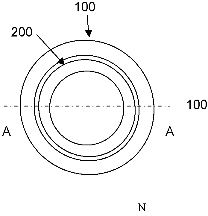
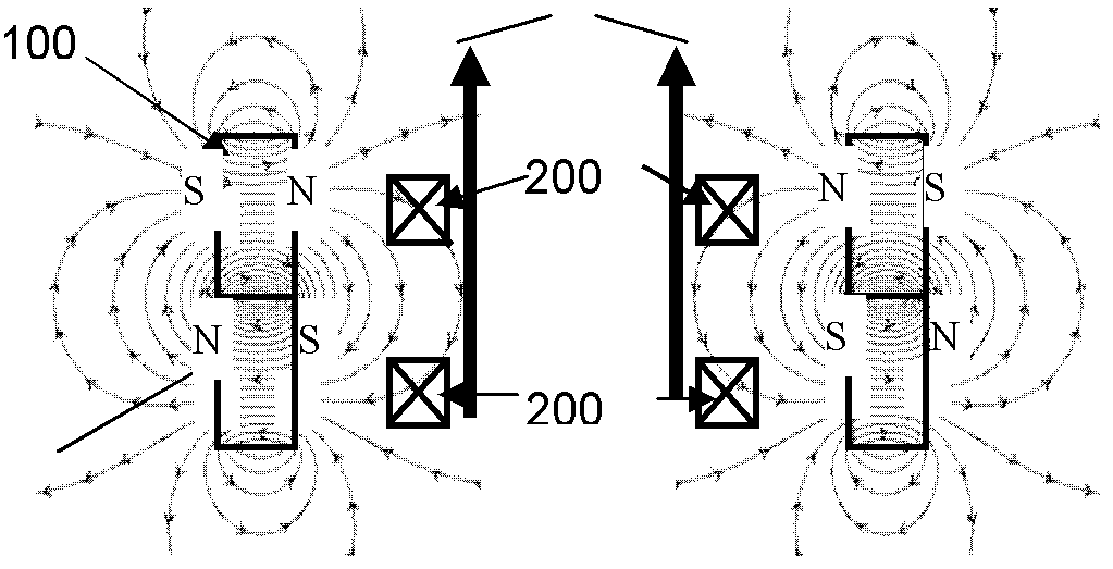
[0051] Such as Image 6 As shown, it is the third embodiment of the present invention. In this embodiment, there is one coil 200, and its shape is roughly square. The magnet 100 is composed of a square magnet and four triangular magnets. The square magnet and four triangular magnets N-poles or S-poles are arranged opposite to each other, and there is a gap left. The lines connecting the north and south poles of all the magnets 100 are roughly parallel to each other and roughly perpendicular to the plane of the coil 200. The coil 200 passes through the gap between each pair of magnets at the same time. The magnets in this embodiment are not arranged in pairs, but one magnet forms a magnet pair with four magnets respectively. From this extension, other implementations are possible, and one magnet can also be formed with two or three or five magnets respectively. Pair of magnets.

[0052] combine Figure 7a The schematic cross-section shown and Image 6 b. Schematic diagram of...


PUM


Abstract

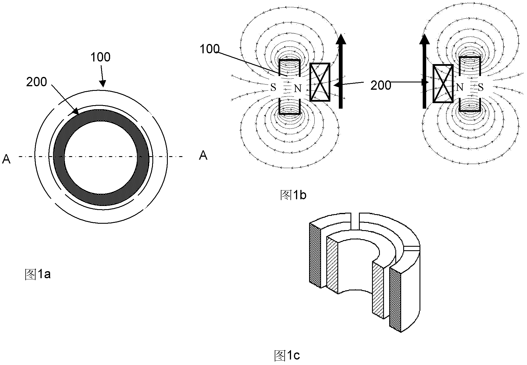
An electromagnetic driving device comprises at least two magnets and at least one coil. Magnetizing directions of the magnets are the same or opposite and are perpendicular to the plane of the coil roughly, the magnets are arranged in a manner of keeping the same polarity opposite while reserving a gap between the magnets, and at least a part of the coil is disposed in the gap between the two magnets wich are arranged oppositely. An electromagnetic lens driving device comprises a frame cover, a lens support, a coil, at least two magnets and a spring, wherein at least a part of the lens support is mounted in the frame cover, the coil is mounted on the lens support, and the magnets are fixed on the frame cover. The sizes of a voice coil motor and a voice coil motor lens driving device are small, operation efficiency is high, the coil can be driven to move by a small quantity of current, and thus energy is saved while size is reduced.

Description

technical field [0001] The present invention relates to a voice coil motor actuator for driving a camera lens, and more particularly, to a voice coil motor actuator for controlling movement of a camera lens along an optical axis. Background technique [0002] The camera functions of mobile phones are becoming more and more perfect, and their applications are becoming more and more extensive. Among them, the autofocus function of mobile phone cameras has increasingly become a standard configuration function of mobile phones, and this function is usually realized by driving the camera lens of the mobile phone to move along the optical axis with a voice coil motor lens driving device. Voice coil motors use energized coils to generate electromagnetic forces of different directions and intensities in a magnetic field to move the lens. [0003] In recent years, some relatively successful voice coil motor lens drive devices have been developed on the market. To sum up, the core s...

Claims


Application Information

Patent Timeline
Patent Type & Authority Applications(China)
IPC IPC(8): H02K33/18G02B7/04G03B30/00
CPCH02K41/0356G02B7/08
Inventor 林小军
Owner 林小军
Learn More