
Apparatuses for reducing the sensitivity of an optical signal to polarization and methods of making and using the same

An optical signal and signal technology, applied in the field of optical signal transmission and/or reception, can solve problems such as the influence of reflected light wave polarization degree

Active Publication Date: 2013-01-02
SOURCE PHOTONICS CHENGDU
View PDF14 Cites 8 Cited by
  • Summary
  • Abstract
  • Description
  • Claims
  • Application Information

AI Technical Summary

Problems solved by technology

In addition, placing the mirror at 45 degrees in the optical receiver requires precise positioning during the manufacturing process, and small changes in the mirror angle can also have a large impact on the degree of polarization in the reflected light wave

Method used


Image

  • Apparatuses for reducing the sensitivity of an optical signal to polarization and methods of making and using the same
  • Apparatuses for reducing the sensitivity of an optical signal to polarization and methods of making and using the same
  • Apparatuses for reducing the sensitivity of an optical signal to polarization and methods of making and using the same

Examples


Embodiment Construction

[0021] Various embodiments of the invention will be referenced in detail. Referenced examples are explained in the accompanying drawings. The invention will be illustrated by the examples which follow, but the invention is not limited to the description of these examples. On the contrary, the invention is intended to cover alternatives, modifications and equivalents which may be included within the spirit and scope of the invention as defined by the appended claims. Moreover, in the following detailed description of the invention, numerous specific details are specified in order to provide a thorough understanding of the invention. However, it will be apparent to one skilled in the art that the present invention may be practiced without these specific details. In other instances, well-known methods, procedures, components, and circuits have not been described in detail so that various aspects of the invention may be described in detail.

[0022] Likewise, for convenienc...


PUM

PropertyMeasurementUnit
angle of incidenceaaaaaaaaaa

Abstract

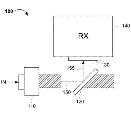
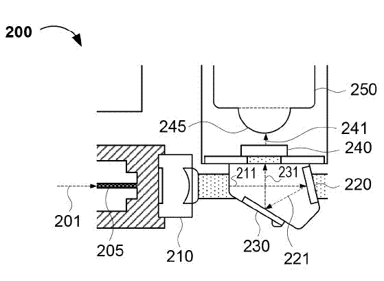
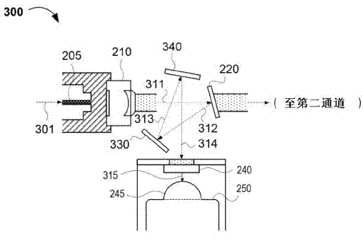
Methods and apparatuses for reducing the sensitivity of an optical signal to polarization. The method generally includes (i) reflecting the optical signal from a first mirror at a first angle relative to the optical signal to a second mirror at a second angle, and (ii) further reflecting the reflected optical signal from the second mirror to a receiver. The apparatus generally comprises (i) a first mirror at a first angle relative to an incident optical signal and configured to reflect the incident optical signal, (ii) a second mirror at a second angle configured to further reflect the reflected optical signal to a first receiver, and (iii) a lens configured to focus andor collimate the optical signal or the reflected optical signal. The first angle is configured to reduce polarization of the reflected optical signal, thereby maximizing the intensity or power of the optical signal.

Description

technical field [0001] The present invention relates to optical signal transmission and / or reception. More specifically, embodiments of the invention are applicable to methods and apparatus for reducing the polarization sensitivity of optical signals (eg, in receivers or transceivers). Background technique [0002] When the electric field vector of the light wave is perpendicular to the direction of light propagation in the predetermined plane, the light wave will be linearly polarized. The direction of the predetermined plane is the polarization direction. For example, a horizontally polarized light wave has a vertical amplitude of 0, while a vertically polarized light wave has a horizontal amplitude of 0. Unpolarized light waves travel in more than one plane. Polarization of a light wave (eg, a light signal) occurs when a non-metallic medium (eg, a beam splitter) reflects the light wave into reflected and refracted light. When polarization occurs via reflection (for ex...

Claims


Application Information

Patent Timeline
Patent Type & Authority Applications(China)
IPC IPC(8): G02B6/42G02B30/25
CPCG02B6/42G02B6/4201
Inventor 摩西·阿米特
Owner SOURCE PHOTONICS CHENGDU
Learn More