Light guide with decoupling portion and shield for collecting decoupled rays

A technology of light guide and light, which is applied in the field of light guide, can solve the problems of unfavorable aesthetic aspects of photometric view

Active Publication Date: 2013-01-02
VALEO VISION SA
View PDF7 Cites 13 Cited by
  • Summary
  • Abstract
  • Description
  • Claims
  • Application Information

AI Technical Summary

Problems solved by technology

This area presents a strong non-uniform illumination beam and is therefore disadvantageous from a photometric point of view and from an aesthetic point of view

Method used


Image

  • Light guide with decoupling portion and shield for collecting decoupled rays
  • Light guide with decoupling portion and shield for collecting decoupled rays
  • Light guide with decoupling portion and shield for collecting decoupled rays

Examples


Embodiment Construction

[0046] In the following description, terms that quantify the position of certain elements, such as "front", "rear", "in front", "behind", "horizontal", "vertical ", etc., represent the specific layout of the accompanying drawings. But these terms should not be interpreted strictly and absolutely, but relatively and comparatively. In fact, the signaling devices described herein may be oriented differently in practice without departing from the invention in any way.

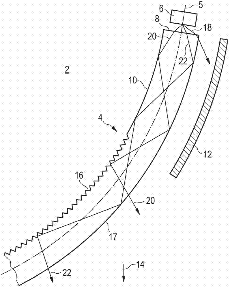
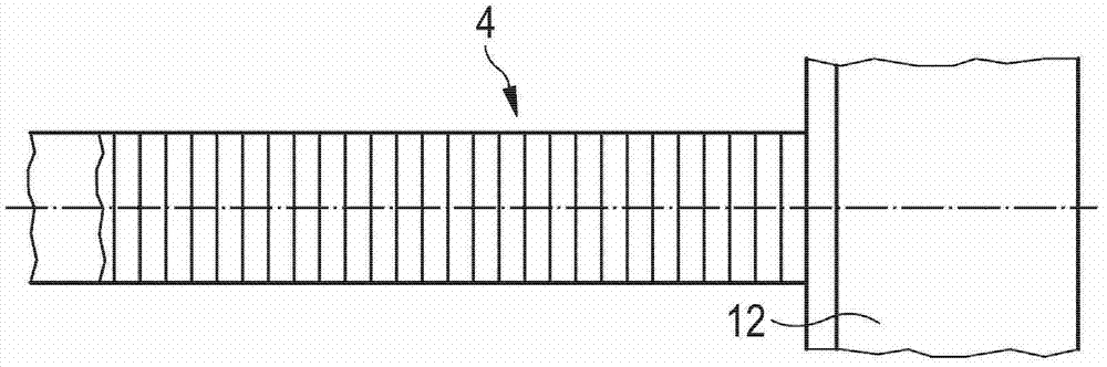
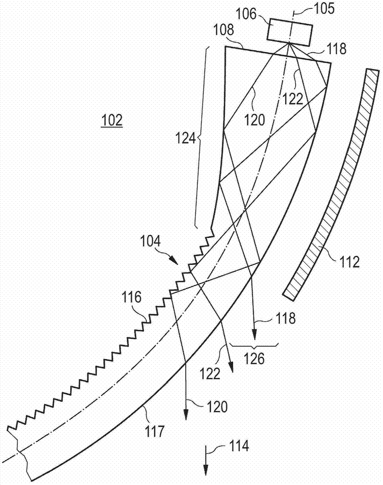
[0047] in the attached Figure 5 , 7, 8, 9, 10, 11, 12 and 13, some of the constituent elements of the lighting device and light guide illustrated in Figures 1 to 4 Corresponds to the constituent elements in . Use consistent numbering to designate these various components, remembering that in addition to incrementing by 1000, Figure 5 The reference designation corresponds to the figure 1 reference number. This also applies to the attached Figure 9 , in the attached Figure 9 increase by 10000, for the at...


PUM


Abstract

The invention discloses a light guide with a decoupling portion and a shield for collecting decoupled rays. The light guide comprises an external surface forming a guiding diopter. The light guide is suitable for guiding light rays by reflection on the guiding diopter. The light guide comprises at least one decoupling portion (1030), with a refraction decoupling diopter (1034) arranged so as to refract light rays to decouple them from the light guide, and thus transmit them out of the light guide through the refraction decoupling diopter.

Description

technical field [0001] The present invention relates to light guides, which may be rectilinear or have curved profiles. The invention also relates to a lighting and / or signaling device, in particular for a vehicle, comprising a light guide. Background technique [0002] In the field of automotive lighting and signaling, the use of light guides is becoming more and more common. In practice, the light guide presents the advantage of being able to assume a wide variety of geometries and bringing the illuminated surface even to hard-to-reach areas of the lighting and / or signaling device, thereby contributing to the style of the device. [0003] In current applications, the term "light guide" is used to denote a transparent or translucent block within which light travels in a controlled manner from one of the two ends of the light guide (referred to as the "input face") to at least one output face. Controlled propagation is generally performed by internal reflection on differe...

Claims


Application Information

Patent Timeline
Patent Type & Authority Applications(China)
IPC IPC(8): G02B6/00F21S8/10F21V8/00F21V7/00
CPCG02B6/0045F21S48/2237G02B6/002G02B6/0053G02B6/0018G02B6/001G02B6/0038F21S43/237F21S43/245F21S43/249F21S43/235F21S43/236F21S43/241
Inventor 文森特·高德比伦
Owner VALEO VISION SA
Why Eureka
Try Eureka