A combined welding stand

A combined, welding-position technology, applied in welding equipment, auxiliary welding equipment, welding/cutting auxiliary equipment, etc., can solve the problems of increasing the labor intensity of welders, difficult to ensure the training effect, and increasing the work intensity, and achieve convenient installation and Welding operation, improving training assessment effect, saving training space effect

Active Publication Date: 2015-09-16
ENERGY CHINA APCC
View PDF5 Cites 1 Cited by
  • Summary
  • Abstract
  • Description
  • Claims
  • Application Information

AI Technical Summary

Problems solved by technology

At present, the welding position frame used in training or assessment is fixed. Since it cannot be lifted and rotated, it is necessary to replace various fixtures when adjusting the height and space angle of the weldment, resulting in the inability to fix the weldment effectively and increasing the labor intensity of the welder.
In addition, qualified welders at different levels need to master the welding of corresponding types of workpieces, such as small-diameter tube cross-barrier welding, small-diameter tube straight-line barrier welding, medium-diameter tube welding, plate welding, etc., which require different welding fixtures. Frequent replacement of fixtures or welding positions not only increases the work intensity, but also wastes valuable training or assessment time, which is not efficient; it is also easy to cause operational errors, it is difficult to ensure effective training effects, and cannot meet the power industry standard DL / T679 -2012 "Welder Technical Examination Regulations" and TSG Z6002-2010 "Special Equipment Welding Operator Examination Rules" requirements for the spatial location of weldments for training and examination of welders of various levels

Method used


Image

  • A combined welding stand
  • A combined welding stand

Examples


Embodiment Construction

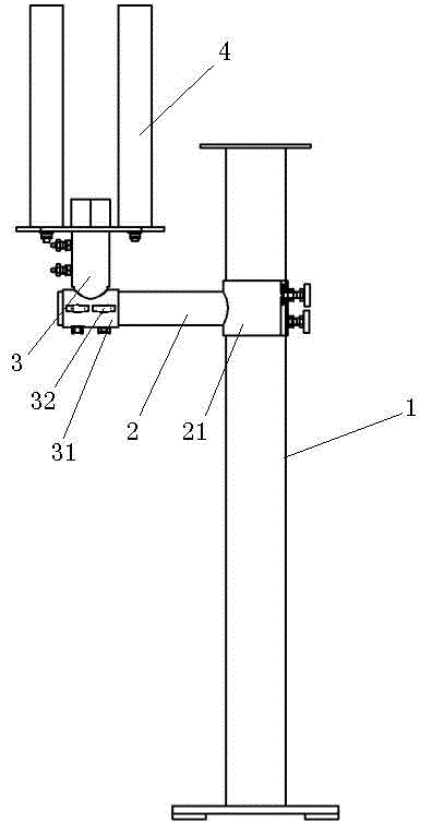
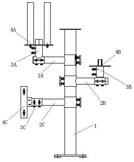
[0016] Such as figure 1 A combined welding position frame shown includes a column 1, and a welding position mechanism is provided on the column 1. The welding position mechanism includes an arm 2, and the arm 2 is positioned by a height provided on the column 1. The hole and the column 1 are fixed by bolts; the other end of the arm 2 is provided with a movable rod 3 , and the other end of the movable rod 3 is fixedly connected with a clamp 4 . One end of the arm 2 is provided with a sliding sleeve 21, and the arm 2 is movably sleeved on the column 1 through the sliding sleeve 21. The sliding sleeve 21 is provided with a bolt hole corresponding to the height positioning hole. One end of the movable rod 3 is provided with a sleeve 31, and the sleeve 31 is provided with an angle positioning hole 32. The movable rod 3 is movably sleeved on the arm rod 2 through the sleeve 31 and fixed by bolts through the angle positioning hole 32. The clamp 4 is a small-diameter tube cross barri...


PUM


Abstract

The invention provides a combination type welding frame which comprises a column. At least one welding mechanism is arranged on the column and comprises an arm rod fixed with the column in bolt mode through a height location hole arranged on the column. A movable rod is arranged at the other end of the arm rod, and a clamp is fixedly connected with the other end of the movable rod. The combination type welding frame is simple in structure, flexible in assembly and capable of adjusting height and angle of a clamp and facilitates installation and welding operation of the clamp.

Description

technical field [0001] The invention relates to the field of welding technology, in particular to a combined welding position frame suitable for training and examination of welders of different levels. Background technique [0002] Welding is the use of welding materials (welding rods or wires) to connect two or more workpieces to be welded into a whole under high temperature or high pressure conditions, so that an interatomic bonding force is generated between them to form a permanent connection. Welding is widely used in modern processing and manufacturing industries. It can be used for both metals and non-metals. The welding quality is the guarantee for the safe operation of products in industrial enterprises, so there are strict requirements for welders' operating skills. With the promulgation and implementation of TSG Z6002-2010 "Special Equipment Welding Operator Assessment Rules", the assessment of welder's operating skills will become more standardized. At present, ...

Claims


Application Information

Patent Timeline
Patent Type & Authority Patents(China)
IPC IPC(8): B23K37/00B23K37/04
Inventor 赵军刘亚芬周生华朱立新李绍明陈绍华高胜华班伟
Owner ENERGY CHINA APCC
Why Eureka
Try Eureka