Multi-polar resolver

A resolver and rotor technology, applied in the direction of transformers, inductors, magnetic circuit rotating parts, etc., can solve the problems of complex structure and inapplicability of resolver, and achieve the effects of simple structure, reduced production cost and high degree of mechanization

Active Publication Date: 2012-12-26
苏州和鑫电气股份有限公司
View PDF4 Cites 6 Cited by
  • Summary
  • Abstract
  • Description
  • Claims
  • Application Information

AI Technical Summary

Problems solved by technology

[0003] In order to solve the problem that the existing rotary transformer used for angle measurement is complex in structure and not suitable for multi-pole angle measurement where the number of pole pairs is 2-12 pairs of poles, the present invention provides a multi-pole rotary transformer with simple structure, which is used for Multi-pole (2-12 pairs of poles) angle measurement or multi-pole angle position sensor

Method used


Image

  • Multi-polar resolver
  • Multi-polar resolver
  • Multi-polar resolver

Examples


Embodiment Construction

[0026] The present invention will be further described below in conjunction with the accompanying drawings. The following examples are only used to illustrate the technical solutions of the present invention more clearly, and cannot be used to limit the protection scope of the present invention.

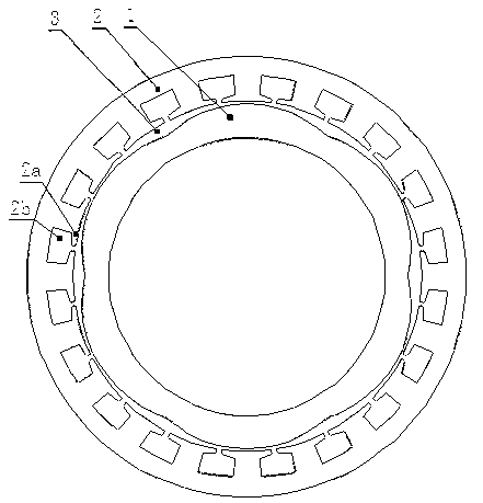
[0027] like figure 1 and figure 2 As shown, the multi-stage rotary transformer of the present invention includes a rotor 1 , a stator 2 , an excitation winding 4 , a sine winding 5 , and a cosine winding 6 . Both the rotor 1 and the stator 2 are formed by laminating multiple silicon steel sheets with high magnetic permeability. An air gap 3 is uniformly provided between the inner circular surface of the stator 2 and the outer circular surface of the rotor 1 . The outer circular surface of the rotor 1 is evenly provided with P wave crests and wave troughs. The wave crests and the wave troughs are smoothly connected to each other to form the wavy outer circular surface of the roto...


PUM


Abstract

The invention discloses a multi-polar resolver, comprising a rotor and a stator and further comprising an exciting winding, a sinusoidal winding and a cosine winding which wind around the stator; wherein the outer circle surface of the stator is uniformly provided with P wave peaks and P wave troughs; the inner circle surface of the stator is provided with teeth and slots at regular intervals; each tooth is uniformly wound with the exciting windings at the first layer which are serially connected in a positive and negative alternation manner; the sinusoidal windings at the second layer are wound above the exciting windings at the first layer; the cosine windings at the third layer are wound above the sinusoidal windings at the second layer; and moreover, half of the sinusoidal windings at the second layer interchange the layer with half of the cosine windings at the third layer; constant voltage sinusoidal AC current is applied to the exciting wind, the electromotive forces output by the sinusoidal windings and the cosine windings respectively make a P-time sine and cosine change along with the rotor rotation angle, thus the output winding has the function of a two-phase multi-polar resolver. The multi-polar resolver is simple in structure and high in production mechanization degree, and the production cost of the multi-polar resolver is greatly lowered.

Description

technical field [0001] The invention relates to a rotary transformer, in particular to a multi-pole rotary transformer. Background technique [0002] The traditional rotary transformer used for angle measurement has its excitation winding and output winding set on the rotor and stator respectively. It is a brushed (contact) structure. To achieve brushless, a toroidal coupling transformer ( Referred to as "ring change"), in this way, the structure of the resolver is complicated; and most of the pole pairs of this brushless resolver are dominated by a pair of poles. For multi-pole rotary transformers, it is extremely difficult to design and manufacture, and it is almost impossible. Another existing "vernier type resolver", the output winding of the excitation winding is on the stator, which realizes brushless, but the number of pole pairs P of this type of vernier type resolver is very large, and the minimum pole pairs are mostly 16 pairs. It is very difficult to manufacture...

Claims


Application Information

Patent Timeline
Patent Type & Authority Applications(China)
IPC IPC(8): H01F38/18H02K1/22H02K3/12H02K1/12
Inventor 胡岗姜全荣何平
Owner 苏州和鑫电气股份有限公司
Why Eureka
Try Eureka