Lens continuous moving anti-collision device and method

An anti-collision device and interlocking technology, which is applied in the field of optical instrument devices, can solve problems such as mutual collisions and excessively fast motor speeds

Inactive Publication Date: 2012-12-26
ASIA OPTICAL CO INC
View PDF8 Cites 5 Cited by
  • Summary
  • Abstract
  • Description
  • Claims
  • Application Information

AI Technical Summary

Problems solved by technology

[0004] The technical problem to be solved by the present invention is to provide a lens linkage anti-collision device to overcome the above-mentioned zoom lens barrel and the focusing lens group in the prior art, which are easy to collide with each other. During the interlocking process of the focusing lens group, due to the speed of any one of the motors being too fast or too slow, there is a problem of collision with each other

Method used


Image

  • Lens continuous moving anti-collision device and method
  • Lens continuous moving anti-collision device and method
  • Lens continuous moving anti-collision device and method

Examples


Embodiment Construction

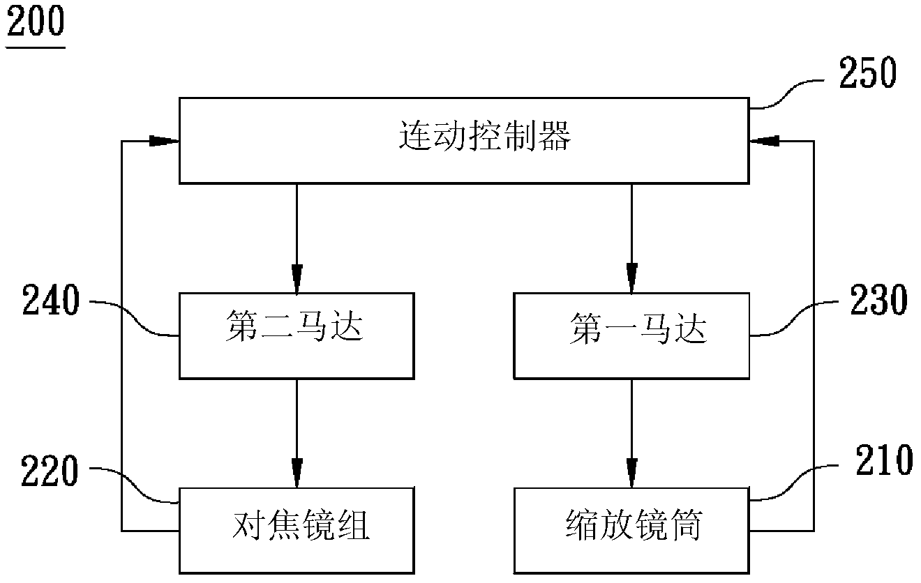
[0018] figure 1 A functional block diagram of a lens-linked anti-collision device according to an embodiment of the present invention is shown. Such as figure 1 As shown, the lens linkage anti-collision device 100 includes an optical module 110 , a driving module 120 and a linkage controller 130 . The linkage controller 130 controls the drive module 120 by means of slope linkage, so as to avoid collision damage to the internal components of the optical module 110 .

[0019] The optical module 110 includes a zoom lens barrel 111 and a focusing lens group 112 . The focus lens group 112 is located in the zoom lens barrel 111 , and the user can change the position of the focus lens set 112 in the zoom lens barrel 111 to change the focal length and achieve the effect of focusing on the object.

[0020] The driving module 120 is used to drive the optical module 110 to move, wherein the driving module 120 includes a first motor 121 and a second motor 122 . The first motor 121 is ...


PUM


Abstract

The invention relates to a lens continuous moving anti-collision device and a method. The lens continuous moving anti-collision device comprises an optical module, a driving module and a linkage controller, wherein the optical module comprises a telescopic lens cone and a focusing lens set arranged in the telescopic lens cone; the driving module is used for driving the optical module to displace, wherein the driving module comprises a first motor and a second motor; the first motor is used for driving the telescopic lens cone to axially telescopically displace; the second motor is used for adjusting a position of the focusing lens set in the telescopic lens cone; and the linkage controller is used for controlling linkage between the first motor and the second motor, as well as controlling a rotating speed of the first motor to reach a state of being in direct proportion to the rotating speed of the second motor, so that the telescopic lens cone and the focusing lens set cannot be collided to each other during a linkage process.

Description

technical field [0001] The invention relates to an optical instrument device, and in particular to a lens linkage anti-collision device and a method thereof. Background technique [0002] In recent years, it has become increasingly common for handheld devices such as mobile phones, PDAs, digital cameras, and video cameras to be equipped with imaging modules. The imaging module has been faced with the dual requirements of higher image quality and miniaturization. When using a handheld device for image capture, zooming and focusing of the lens are necessary functions of each optical imaging module. [0003] The existing design uses different motors to drive the zoom lens barrel and the focus lens group to make them store and unfold. This method has its own driving motor and mechanism for both the zoom lens barrel and the focus lens group. When the rotational speed of the first motor is too fast or too slow, the zoom lens barrel and the focus lens group will collide with each...

Claims


Application Information

Patent Timeline
Patent Type & Authority Applications(China)
IPC IPC(8): G03B17/04G03B17/12H04N5/232
Inventor 陈锡坚杨明骑洪嘉村
Owner ASIA OPTICAL CO INC
Why Eureka
Try Eureka