
High temperature large-caliber flue gas pipeline inlet airtight device used in cement industry

A cement industry, pipeline import technology, applied in the direction of lift valve, valve details, engine components, etc., can solve the problems of inability to meet low leakage requirements, large leakage rate of ventilation butterfly valves, large cost of driving components, etc., to achieve reduced opening force, sealing Good performance and reduced output force

Inactive Publication Date: 2012-12-26
YANGZHOU GAOBIAN MACHINE
View PDF0 Cites 0 Cited by
  • Summary
  • Abstract
  • Description
  • Claims
  • Application Information

AI Technical Summary

Problems solved by technology

[0002] The working environment temperature of the high-temperature and large-diameter flue gas pipe inlet airtight device used in the cement industry is above 550°C, and the external leakage requirement is very high, generally 0-0.3%, and the diameter is large (generally above 2000mm, up to 5000mm). Currently, it is usually used Welded high-temperature ventilation butterfly valves are used instead, but the leakage rate of ventilation butterfly valves is very large, between 1.5% and 2.5%, which cannot meet the low leakage requirements; It is negative pressure, the medium in the pipeline has a suction force on the valve cover, the larger the pipeline area, the greater the suction force, the greater the negative pressure, the greater the suction force, so the required opening force is large, the greater the opening and closing force, the higher the cost of the driving parts
At present, there is a lack of a high-temperature large-diameter flue gas pipe inlet special sealer with strong high-temperature resistance, reliable sealing, and high cost performance.

Method used


Image

  • High temperature large-caliber flue gas pipeline inlet airtight device used in cement industry
  • High temperature large-caliber flue gas pipeline inlet airtight device used in cement industry
  • High temperature large-caliber flue gas pipeline inlet airtight device used in cement industry

Examples


Embodiment Construction

[0015] The specific embodiment of the present invention will be further described below in conjunction with accompanying drawing:

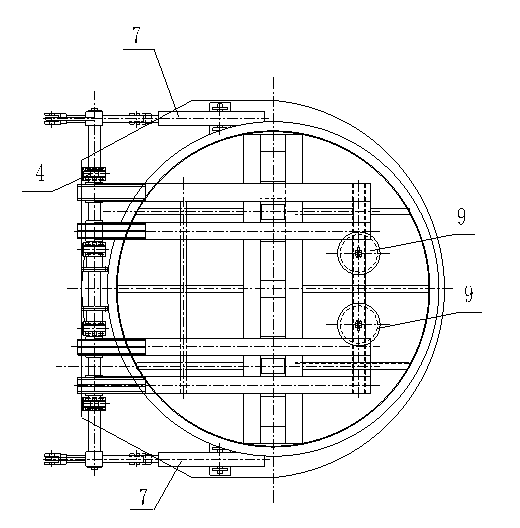
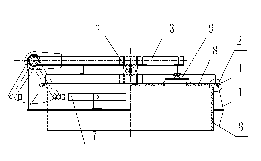
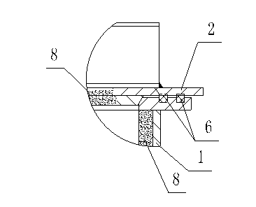
[0016] Such as figure 1 , 2 Shown in and 3: a high-temperature large-caliber flue gas pipeline inlet sealer for the cement industry, including a valve body 1, a valve cover 2, a force arm assembly 3, a supporting part 4, a pin shaft 5, a seal 6, a driving part 7, The high temperature resistant layer 8 and the pressure relief part 9, the inner opening of the valve body 1 is provided with a sealing slope, the upper end surface of the valve body 1 is provided with an installation groove, and a seal 6 is arranged in the installation groove, and the sealing slope and the inner wall of the installation groove Lined with a high temperature resistant layer 8, the sealing slope and the lower plane in contact with the seal 6 are lined with a high temperature resistant layer 8, the valve cover 2 is connected with the arm assembly 3 through a pin shaft 5...


PUM


Abstract

The invention discloses a high temperature large-caliber flue gas pipeline inlet airtight device used in cement industry. The airtight device comprises a valve body, a valve cover, an actuating arm assembly, a bearing part, a pin shaft, a sealing part, a driving part, a high temperature resistant layer and a pressure relief part; an inclined sealing surface is arranged at the inner opening of the valve body; a mounting groove is arranged on the upper end surface of the valve body; the sealing part is arranged in the mounting groove; the high temperature resistant layer is lined on the inclined sealing surface and the inner wall of the mounting groove; the high temperature resistant layer is lined on the inclined sealing surface and a lower plane in contact with the sealing part; the valve cover is connected with the actuating arm assembly via the pin shaft; a pin shaft hole is U-shaped; the pressure relief part is installed on the valve cover; the pressure relief part comprises a pressure relief part valve cover connected with the actuating arm assembly; the actuating arm assembly is connected with the bearing part; and the bearing part is connected with the driving part. The airtight device relieves the pressure firstly, reduces the acting force of the negative pressure to the valve cover, save manufacturing cost, and has safe and reliable structure and good sealing property.

Description

technical field [0001] The invention relates to a sealing device for a flue gas discharge port, in particular to a sealing device for the inlet of a high-temperature and large-diameter flue gas pipe used in the cement industry. Background technique [0002] The working environment temperature of the high-temperature and large-diameter flue gas pipe inlet airtight device used in the cement industry is above 550°C, and the external leakage requirement is very high, generally 0-0.3%, and the diameter is large (generally above 2000mm, up to 5000mm). Currently, it is usually used Welded high-temperature ventilation butterfly valves are used instead, but the leakage rate of ventilation butterfly valves is very large, between 1.5% and 2.5%, which cannot meet the low leakage requirements; It is negative pressure, the medium in the pipeline has a suction force on the valve cover, the larger the pipeline area, the greater the suction force, the greater the negative pressure, the great...

Claims


Application Information

Patent Timeline
Patent Type & Authority Applications(China)
IPC IPC(8): F16K1/24F16K1/32F16K27/02F16K31/44
Inventor 吴有还
Owner YANGZHOU GAOBIAN MACHINE
Learn More