
Spill-proof pot cover

An anti-overflow and pot cover technology, which is applied in the field of kitchen utensils, can solve the problems of not being able to prevent overflow, cannot form an airtight effect, foreign objects fall into the pot, etc., achieve good anti-overflow effect, save time and energy, and is not easy broken effect

Inactive Publication Date: 2012-12-26
广州市越秀日达有限公司
View PDF6 Cites 25 Cited by
  • Summary
  • Abstract
  • Description
  • Claims
  • Application Information

AI Technical Summary

Problems solved by technology

[0002] At present, most of the silicone pot lids on the market can form a sealing effect with the pot, and the soup often overflows during cooking, and the user needs to spend more energy to adjust the pot lid
[0003] In addition, some silicone pot covers have vent holes on the cover body to discharge water vapor and heat. With this design, since the vent holes on the pot cover cannot be closed, if the opening is too large, foreign objects may fall into the pot. When the water has not reached the boiling point, water vapor can be discharged through the vent holes, and the heat will be dissipated, prolonging the heating time and wasting energy
That is, if the ventilation hole is opened too large, the heating time will be greatly prolonged, resulting in unnecessary waste of energy; if the opening is too small, it will not be able to play a good anti-overflow effect
[0004] There is also a design that adopts the airtight form of sheet silica gel and silica gel cover, relying on the pressure formed by water vapor to lift the sheet silica gel to achieve the purpose of discharging water vapor and heat, but the silica gel sheet will age and deform after long-term use, and cannot form an airtight seal. The effect is equivalent to opening the ventilation hole

Method used


Image

  • Spill-proof pot cover
  • Spill-proof pot cover
  • Spill-proof pot cover

Examples


Embodiment Construction

[0070] Below in conjunction with accompanying drawing and specific embodiment, the present invention will be further described:

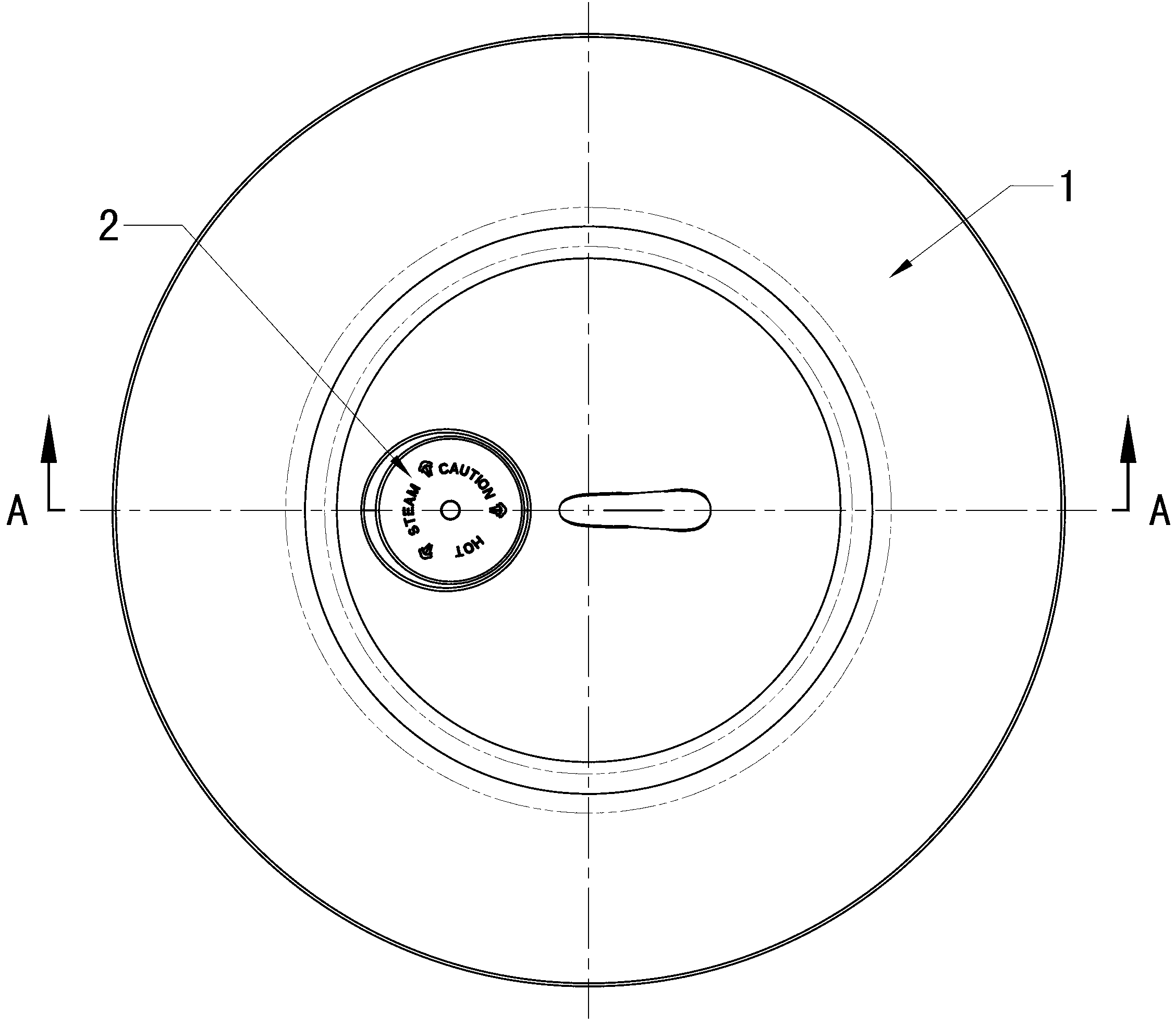
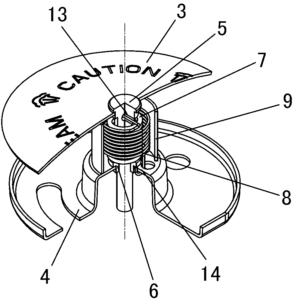
[0071] Such as Figure 1 to Figure 4 The anti-overflow pot cover of the embodiment shown includes a pot cover body 1 and an anti-overflow mechanism 2. The pot cover body 1 is provided with a concave cavity 10 for accommodating the wrapping anti-overflow mechanism 2. The concave cavity 10 can be located at Any part of the lid body area between the handle of the pot lid and the fastening edge of the pot lid; the anti-overflow mechanism 2 includes a top sheet 3, a base 4, a sliding shaft 5, a guide sleeve 6 and elastic parts, and the top sheet 3 is fixed on the sliding shaft 5 and cover the upper opening of the concave cavity 10, the bottom of the concave cavity 10 has a through hole 121; the sliding shaft 5 is inserted into the guide sleeve 6 through the elastic component, and the guide sleeve 6 is fixed on the base 4, and the base 4 has a through ho...


PUM


Abstract

The invention discloses a spill-proof pot cover including a pot cover and a spill-proof mechanism; the pot cover is provided with cavity for containing and enclosing the spill-proof mechanism; the spill-proof mechanism includes a top plate, a base, a sliding shaft and a flexible component; the top plate is fixed on the top of sliding shaft and covers the upper opening of the cavity, and a through hole is arranged at the bottom of the cavity; the sliding shaft penetrates the flexible component and is inserted in the base, and the base is provided with a through hole; the base is detachably embedded at the bottom of the cavity, the through hole at the bottom of the cavity is communicated with the through hole on the base. The spill-proof mechanism in the silicone pot cover is provided with a shape memorizing alloy which opens and closes a vent of the pot cover automatically based on the change of the temperature; and as the whole process is automatically finished, the spill-proof pot cover is convenient to use and saves time and energy for the users.

Description

technical field [0001] The invention relates to a kitchen utensil, more specifically, to a spill-proof pot cover. Background technique [0002] At present, most of the silicone pot lids on the market can form a sealing effect with the pot, and the soup often overflows during cooking, and the user needs to spend more energy to adjust the pot lid. [0003] In addition, some silicone pot covers have vent holes on the cover body to discharge water vapor and heat. With this design, since the vent holes on the pot cover cannot be closed, if the opening is too large, foreign objects may fall into the pot. When the water has not reached the boiling point, the water vapor can be discharged through the vent holes, and the heat will be dissipated thereupon, which prolongs the heating time and wastes energy. That is, if the air hole is opened too large, the heating time will be greatly prolonged, resulting in unnecessary waste of energy; [0004] There is also a design that adopts the...

Claims


Application Information

Patent Timeline
Patent Type & Authority Applications(China)
IPC IPC(8): A47J36/06A47J27/56A47J36/38
CPCA47J27/56A47J36/06
Inventor 欧倩婷
Owner 广州市越秀日达有限公司
Learn More