PWM (pulse width modulation) dimming method and device for LED (light-emitting diode)

A technique of adjusting and adjusting coefficients, which is applied in the field of PWM dimming methods and devices, and can solve the problems of few PWM output ports of single-chip microcomputers.

Inactive Publication Date: 2012-12-19
BSH ELECTRICAL APPLIANCES JIANGSU
View PDF0 Cites 9 Cited by
  • Summary
  • Abstract
  • Description
  • Claims
  • Application Information

AI Technical Summary

Problems solved by technology

[0006] The problem solved by the present invention is to propose a PWM dimming method and device for LEDs to solve the problem of few PWM output ports of existing cheap single-chip microcomputers

Method used


Image

  • PWM (pulse width modulation) dimming method and device for LED (light-emitting diode)
  • PWM (pulse width modulation) dimming method and device for LED (light-emitting diode)
  • PWM (pulse width modulation) dimming method and device for LED (light-emitting diode)

Examples


Embodiment 1

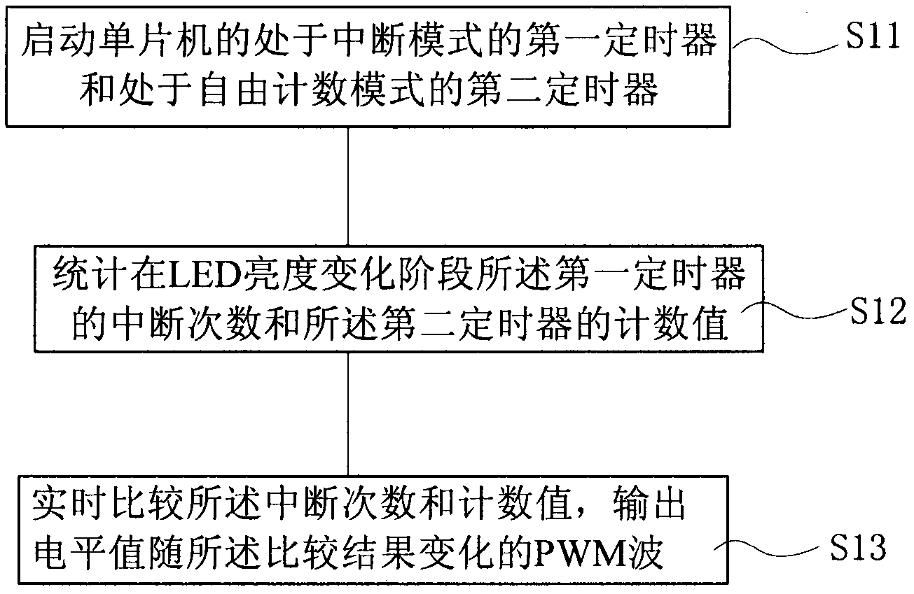
[0078] figure 2 It is a schematic flowchart of a PWM dimming method for controlling a single LED provided by the first embodiment of the present invention.

[0079] combine figure 1 and figure 2 , execute S11, initialize the first timer and the second timer of the single-chip microcomputer;

[0080] The first timer is set to interrupt mode, N times per second; the second timer is set to free counting mode.

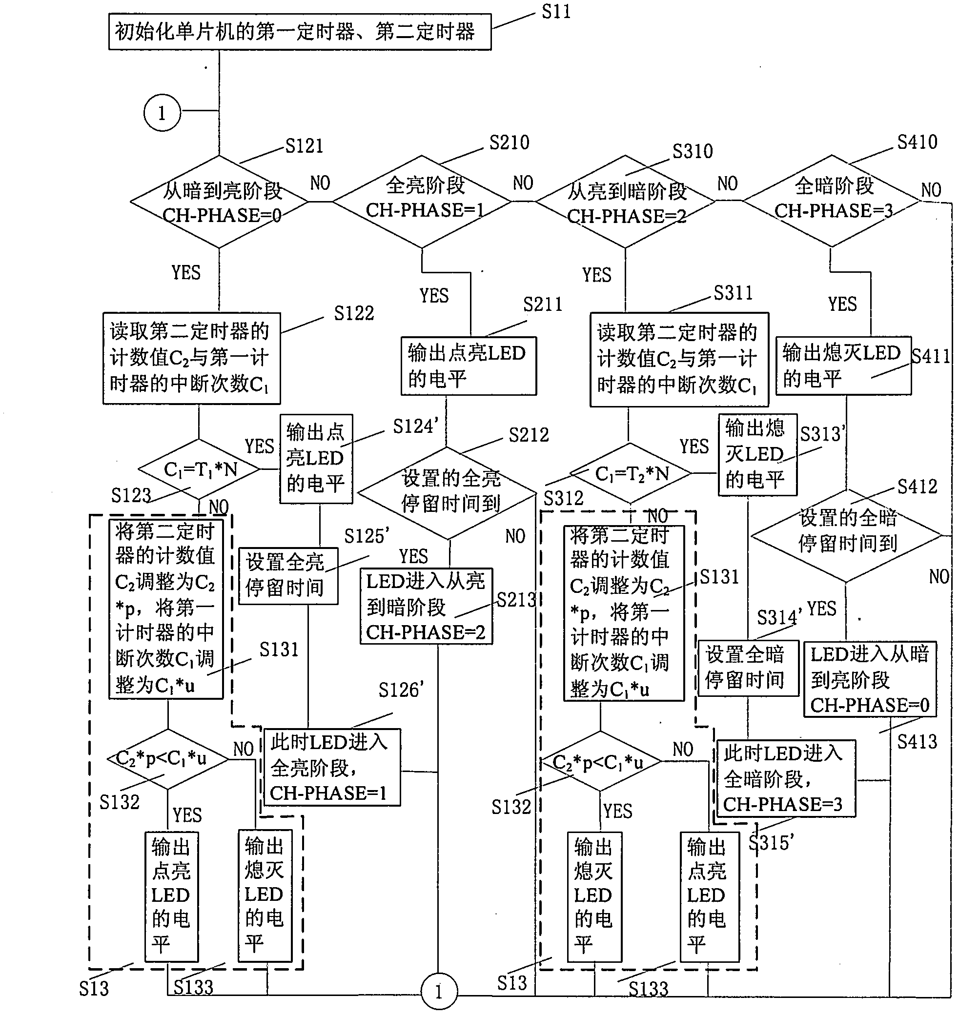
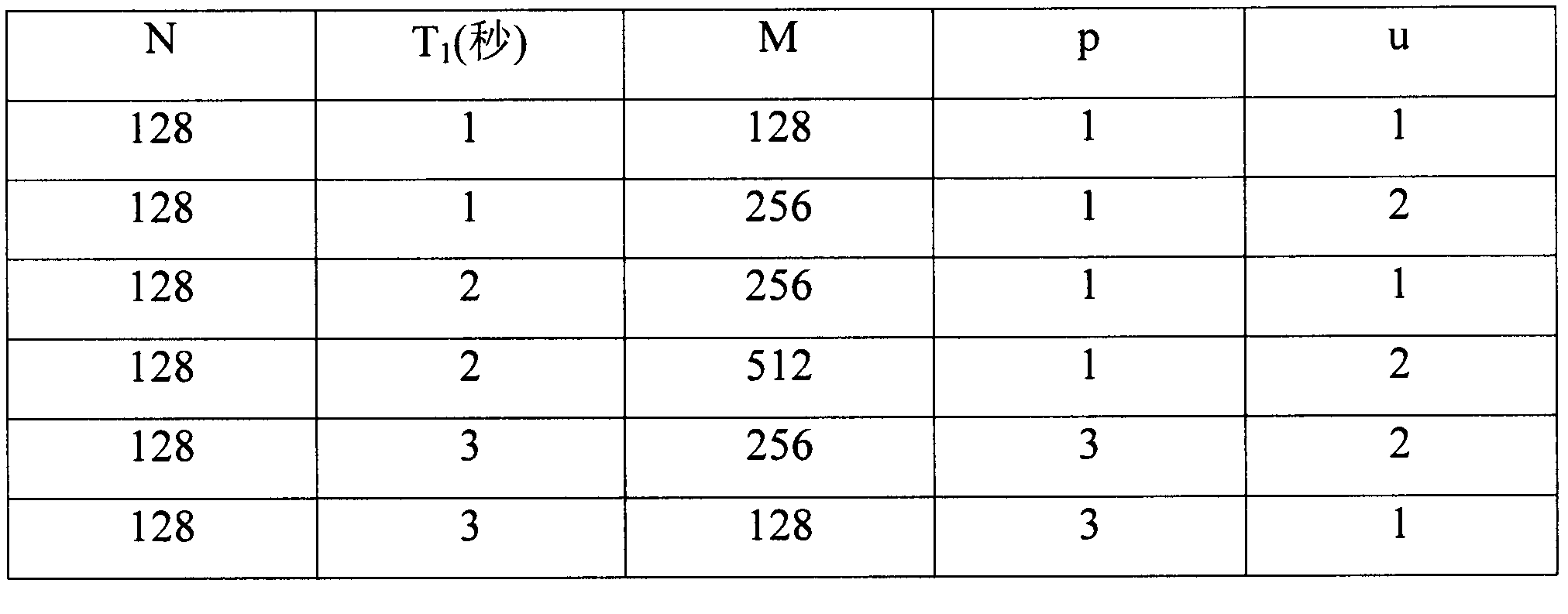
[0081] Then execute S12, count the number of interruptions of the first timer and the count value of the second timer in the LED brightness change stage, including: LED is in the process of changing from dark to bright or from bright to dark, counting all The number of interruptions of the first timer mentioned above, and cleared when the first clear value is counted, the second timer starts to count freely and every first time T 3 The count is increased by 1, and the second timer is cleared when the count reaches the first value M;

[0082] When the LED changes fro...

Embodiment 2

[0130] If it is necessary to control the PWM dimming of two LEDs, and the brightness and dimming methods of the two LEDs and the required time are the same, then apply PWM to the LEDs of the two LEDs.

[0131] If the lighting and dimming methods or required time of the two LEDs are different, the dimming method and device provided in the second embodiment can be used.

[0132] In Figure 8(a), use CH1-PHASE=0 to mark the phase from dark to bright of the first LED, CH1-PHASE=1 to mark the phase when the first LED is fully bright, and CH1-PHASE=2 to mark the phase from the first LED to bright In the dark stage, CH1-PHASE=3 marks the full-dark stage of the first LED. The first LED starts from dark to bright by default, ie CH1-PHASE=0.

[0133] In Figure 8(b), use CH2-PHASE=0 to mark the stage from dark to bright for the second LED, CH1-PHASE=2 to mark the full-bright stage of the second LED, and CH2-PHASE=2 to mark the second LED from bright In the dark stage, CH2-PHASE=3 marks ...


PUM


Abstract

The invention provides a PWM (pulse width modulation) dimming method for an LED (light-emitting diode). The PWM dimming method comprises the following steps: starting a first timer in an interrupt mode and a second timer in a free counting mode of a single chip microcomputer; making statistics on the number of interrupts of the first timer and count values of the second timer during the brightness change stage of the LED; performing at least one zero clearing on the count values of the second timer during the statistical process; and comparing the number of interrupts with the count values in real time, and outputting a PWM wave the level value of which changes along with the comparison result, wherein the PWM wave is applied to the LED for regulating the brightness of the LED. The invention further provides a dimming device corresponding to the method. The PWM dimming method and device for the LED disclosed by the invention can solve the problem of few PWM output ports of the existing cheap single chip microcomputer.

Description

technical field [0001] The invention relates to LED dimming technology, in particular to a PWM dimming method and device for LEDs. Background technique [0002] As the application of LEDs becomes more and more extensive, the control of LEDs becomes more and more important, not only the switch control of LEDs, but also the dimming and brightness control of LEDs. [0003] It can be seen from the V-I characteristics of LEDs that its curve is non-linear, and a voltage of 0.1V can cause a change in current of 100-200mA, which is difficult to control; therefore, LEDs are considered as current-controlling components. Existing LED dimming is generally achieved through PWM, PWM (Pulse Width Modulation) is a pulse width modulation signal, where the "width" is the high level time of the pulse. The PWM signal adjusts the brightness of the LED by changing the high level time of the pulse, that is, the LED on-time. This signal to adjust the brightness is equivalent to adjusting the aver...

Claims


Application Information

Patent Timeline
IPC IPC(8): H05B37/02
CPCY02B20/42Y02B20/40
Inventor 王炳姚庆辉唐小祥张磊磊
Owner BSH ELECTRICAL APPLIANCES JIANGSU
Why Eureka
Try Eureka