
Thermal plasma treatment device and method for low and medium level radioactive solid waste

A radioactive waste and thermal plasma technology, applied in radioactive purification, nuclear engineering, etc., can solve the problems of unfavorable radionuclide capture and control, inability to capture and solidify radionuclide heavy metals, radionuclide diffusion, etc., to achieve The effect of minimizing and stabilizing processing, safe and reliable processing, and reducing storage space

Inactive Publication Date: 2015-10-21
INST OF PLASMA PHYSICS CHINESE ACAD OF SCI
View PDF6 Cites 0 Cited by
  • Summary
  • Abstract
  • Description
  • Claims
  • Application Information

AI Technical Summary

Problems solved by technology

However, the volume reduction effect of these treatment processes is limited, and cannot fundamentally solve the problem of nuclide leaching and diffusion in waste
Incineration can have a significant volume reduction effect on combustible waste, but the problem of dioxin pollution generated during the incineration process has always been the focus of attention
At the same time, because the amount of flue gas produced by incineration is very large, a large amount of flue gas not only increases the burden and cost of tail gas treatment, but also easily causes the further diffusion of radionuclides with the flue gas, which is not conducive to the capture and disposal of radionuclides. control
In addition, the incineration temperature is limited, and the incombustibles produced, such as ash, cannot be melted, and radionuclides and other heavy metals that seriously pollute the environment cannot be captured and solidified.

Method used


Image

  • Thermal plasma treatment device and method for low and medium level radioactive solid waste
  • Thermal plasma treatment device and method for low and medium level radioactive solid waste
  • Thermal plasma treatment device and method for low and medium level radioactive solid waste

Examples


Embodiment Construction

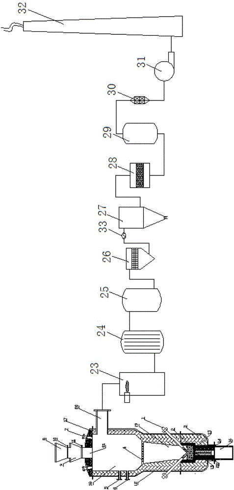
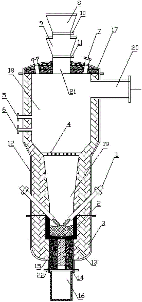
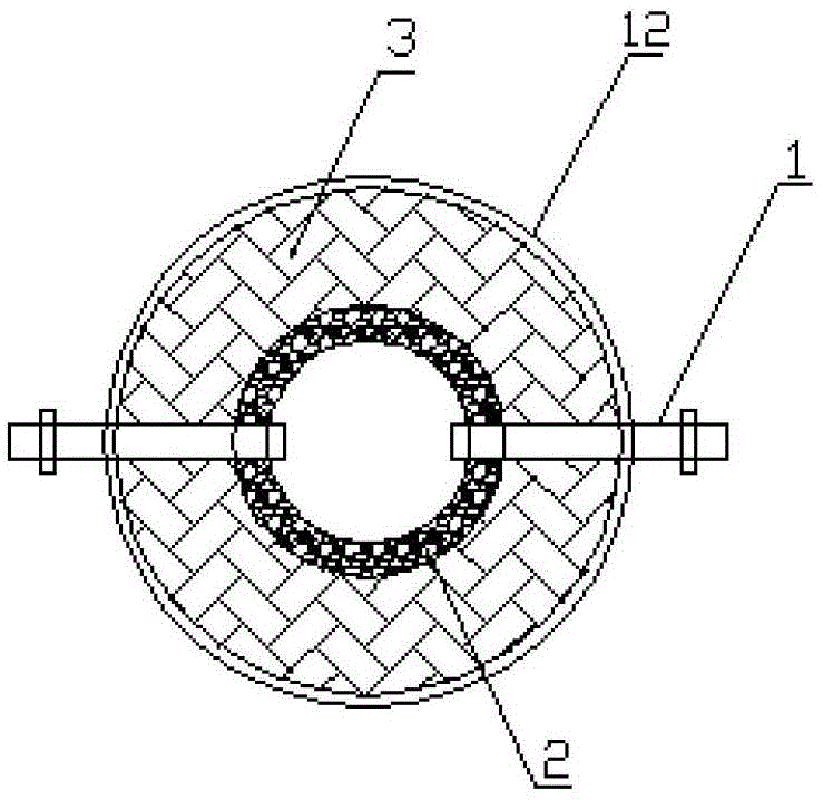
[0028] see figure 1 , 2 3. A device for thermal plasma treatment of low and medium level radioactive solid waste includes a plasma melter-gasifier, the furnace body includes a furnace body 12 and a furnace cover 17 that are interlocked, and the lower part of the furnace body 11 is provided with There is a molten pool crucible 2, the furnace grate 4 set in the furnace divides the furnace into two parts, the upper gasification zone 18 and the lower melting zone 19, and the lower side wall of the furnace body is provided with a plurality of channels extending to the upper end of the molten pool crucible 2. Holes, 2-4 DC plasma torches 1 can be installed as required, and are connected to the plasma discharge power supply through cables. The plasma torch working gas and cooling system are connected to the working gas preparation supply device and cooling water supply device through pipelines; the furnace The cover 17 is provided with a plurality of through holes, and the central t...


PUM


Abstract

The invention discloses a device and a method for disposing low and medium-radioactivity solid waste by hot plasmas. The device comprises a plasma melting gasification furnace, a hot plasma generator, a working gas preparation supply device, a cooling water supply device, a feeding device, a glass solidified body discharging and receiving device, a tail gas purification treatment device and corresponding measuring, controlling and monitoring systems. Organic and inorganic carbonaceous compositions in the waste are gasified by the hot plasmas in a low-temperature area of a hearth, generated ash and inorganic substances in the waste are melted in a high-temperature area of the hearth, added glass organizers are regulated so that radioactive nuclides are stably fixed in glass organizers, and flue gas meets emission requirements of air quality standards after being subjected to purification treatment. Besides, the device and the method for disposing the low and medium-radioactivity waste are environment-friendly, a disposal process is safe and reliable, disposal storage space for radioactive waste can be greatly reduced, national emission standards are met, and the purpose of minimized and stabilized disposal for the radioactive waste is achieved.

Description

technical field [0001] The invention relates to the technical field of volume reduction and solidification treatment of low-level and medium-level radioactive solid waste by utilizing thermal plasma. Background technique [0002] The operation and maintenance of nuclear power plants and the extensive application of radioisotopes in production and physical and chemical experiments, the proper management and safe disposal of various radioactive wastes generated have become one of the important issues that need to be solved urgently. The volume reduction of radioactive waste and the fixation of radionuclides are the focus of radioactive waste treatment. Cement solidification and concrete fixation are the most commonly used radioactive waste treatment methods. However, cement setting and concrete fixation are both compatibilizing processes, although further compression of the waste bales, etc., may be used with compressors. However, the volume reduction effect of these treatme...

Claims


Application Information

Patent Timeline
Patent Type & Authority Patents(China)
IPC IPC(8): G21F9/32
Inventor 倪国华
Owner INST OF PLASMA PHYSICS CHINESE ACAD OF SCI
Learn More