Planetary wheel loading device for ground test equipment of rotating wing plate for aircraft

A loading device and ground test technology, applied in the direction of measuring devices, machine/structural component testing, instruments, etc., can solve problems such as large redundant resistance moment, increased strength and stiffness, and increased geometric dimensions

Active Publication Date: 2014-10-08
中国航天科工集团第六研究院二一〇所
View PDF4 Cites 0 Cited by
  • Summary
  • Abstract
  • Description
  • Claims
  • Application Information

AI Technical Summary

Problems solved by technology

[0004] b) The mechanism selection of the loading device is not reasonable enough. In the process of simulating aerodynamic load loading, there is always an additional redundant load in the horizontal tangential direction (opposite to the direction of velocity), and there is a nonlinear relationship between the force value and the flap deployment angle , due to the longer force arm at the action point, the resulting redundant resistance moment is larger, making it more difficult to deploy the wing in the ground test than in actual work, and the difficulty coefficient varies with the simulated aerodynamic load value of the wing Increase and increase, forcing the gas actuator and related parts in the transmission chain to increase the strength and rigidity, resulting in an increase in geometric size, and ultimately resulting in redundant quality of the product;

Method used


Image

  • Planetary wheel loading device for ground test equipment of rotating wing plate for aircraft
  • Planetary wheel loading device for ground test equipment of rotating wing plate for aircraft
  • Planetary wheel loading device for ground test equipment of rotating wing plate for aircraft

Examples


Embodiment Construction

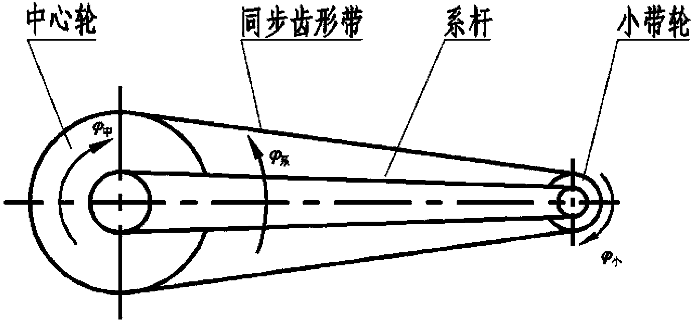
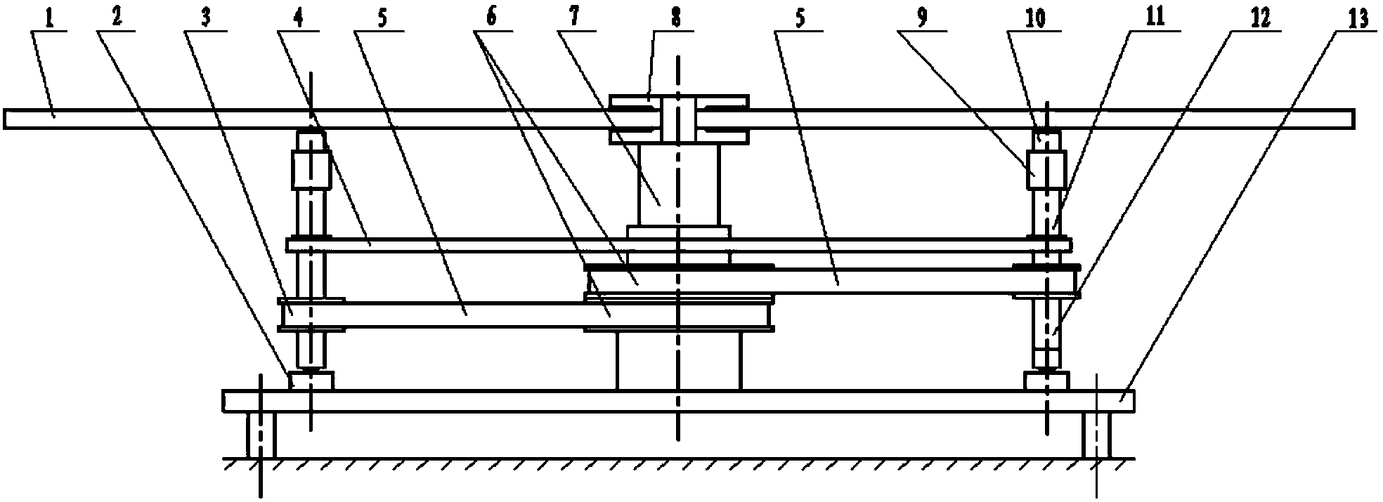
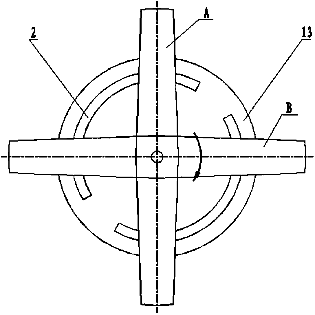
[0021] The present invention comprises a base, a central column and a loading device. The base is vertically provided with a central column, and two wing plates are installed on the top of the central column through a wing plate bracket. The loading device is composed of a ball screw nut and is fixed on a tie rod that can rotate around the column. The lower end of the screw moves along the circular guide rail on the base, and the upper end contacts the lower wing surface of the wing plate through a pressure sensor. As the center of the circle, the two loading devices are symmetrical to the central column. The servo motor drives the tie rod to drive the loading mechanism to rotate synchronously with the wing plate. The center column is coaxially surrounded by a center wheel. The belt drives the small pulley coaxially connected with the lead screw to rotate, and the lead screw drives the nut to move in the axial direction, applying a simulated aerodynamic load to the wing plate. ...


PUM


Abstract

The invention provides a planet gear loading device of a rotary wing plate ground test device for an aircraft, and the planet gear loading device is characterized in that a base is vertically provided with a central upright post, wherein two wing plates are installed on the top end of the central upright post respectively through a wing plate support, a loading device which is formed by a ball screw nut is respectively installed on pressed core positions of two missile wings, each loading device is fixed on a fastening rod which can rotate along the upright post, the lower end of a lead screw moves along an annular lead rail on the base, the upper end of the lead screw is contacted with the wing plates respectively through a pressure sensor, the annular lead rail is centralized on the central upright post, the two loading devices are symmetric to each other about the central upright post, a servo motor drives the fastening rod to drive a loading mechanism to rotate synchronously with the wing plates, a central wheel is coaxially sleeved on the central upright post, the central wheel is driven by another servo motor, the central wheel drives a small belt pulley which is coaxially and fixedly connected with the lead screw to rotate through a synchronic zigzag belt, the nut is driven by the lead screw to move along the axial direction, and an analog pneumatic load is applied to the wing plates. The analog pneumatic load is in linear relation with an unfolding angle of the wing plates, so that no redundant load exists.

Description

technical field [0001] The invention relates to a pneumatic load loading device. Background technique [0002] In the existing ground test equipment for the rotating wing plate of the aircraft, the simulated aerodynamic load loading adopts a flat-plate inclined plane loading device. Due to the limitation of the structural characteristics of this type of loading device itself, there are obvious deficiencies in its working principle, mainly in the following aspects aspect: [0003] a) There is a nonlinear relationship between the simulated aerodynamic load and the flap deployment angle, which can only approximate the aerodynamic lift load borne by the rotating flap, and there are theoretical errors in the design principle; [0004] b) The mechanism selection of the loading device is not reasonable enough. In the process of simulating aerodynamic load loading, there is always an additional redundant load in the horizontal tangential direction (opposite to the direction of velo...

Claims


Application Information

Patent Timeline
Patent Type & Authority Patents(China)
IPC IPC(8): G01M13/00
Inventor 钟世宏
Owner 中国航天科工集团第六研究院二一〇所
Why Eureka
Try Eureka