
System for displaying feet operation of driver based on pressure sensor

A pressure sensor and operation display technology, applied in the direction of signal devices, etc., can solve the problem of no display driver, the driver can't see it easily, etc., to avoid the effect of stepping on the wrong pedal

Inactive Publication Date: 2012-12-19
李良杰
View PDF6 Cites 1 Cited by
  • Summary
  • Abstract
  • Description
  • Claims
  • Application Information

AI Technical Summary

Problems solved by technology

[0003] In order to solve the problem that the existing vehicle does not have a device for displaying the operation of the driver's feet, and the driver cannot conveniently see the operation of his own feet, the present invention provides a pressure sensor-based display system for the driver's foot operations. The position of the driver's feet can be detected through the pressure sensors installed on the clutch pedal, brake pedal and accelerator pedal, and at the same time, the pedals of the driver's feet are displayed on the corresponding position of the display in graphic form, and the driver You can clearly know whether the pedal is correct before stepping on the pedal, thus effectively improving the safety of driving

Method used


Image

  • System for displaying feet operation of driver based on pressure sensor

Examples


Embodiment Construction

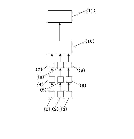
[0010] The pressure sensor-based driver foot operation display system is composed of pressure sensors (1) (2) (3), OP amplifiers (4) (5) (6), A / D converters (7) (8) ( 9) Composed of a single chip (10) and a display screen (11), a pressure sensor is installed on each of the clutch, brake and accelerator pedals. A pressure sensor is installed on each of the above, and the single-chip microcomputer and the display screen are installed on the center console. The signal output end of the pressure sensor is connected to the A / D converter through the OP amplifier, and the signal output end of the A / D converter is connected to the signal input of the single-chip microcomputer. The signal output end of the single-chip microcomputer is connected with the signal input end of the display screen.

[0011] The single-chip computer monitors the status of each pressure sensor in real time, and displays the pedal corresponding to the pressure sensor that detects the existence of pressure on th...


PUM


Abstract

The invention provides a system for displaying feet operation of a driver based on a pressure sensor. The system consists of pressure sensors, an OP (operational) amplifier, an A / D (analogue / digital) converter, a singlechip microcomputer and a display screen; a clutch, a brake and an accelerator pedal are respectively provided with a pressure sensor; in terms of an automatic-catch car which only has a brake and an accelerator pedal, the brake and the accelerator pedal are respectively provided with a pressure sensor; the singlechip microcomputer and the display screen are arranged on a center console; the signal output end of each pressure sensor is connected with the A / D converter through the OP amplifier; the signal output end of the A / D converter is connected with the signal input end of the singlechip microcomputer; and the signal output end of the singlechip microcomputer is connected with the signal input end of the display screen. According to the system provided by the invention, the states of the pressure sensors are monitored by the singlechip microcomputer in real-time, and the pedals corresponding to the pressure sensors with detected pressure are displayed at corresponding positions of the display screen in graphical form.

Description

technical field [0001] The invention relates to a driver foot operation display system based on a pressure sensor. Background technique [0002] The existing vehicle does not have a device that can display the operation of the feet. During the driving process, the driver cannot see the operation of his feet while sitting in the driver's seat, and can only operate the clutch, Brake and accelerator pedals, it is easy to mistakenly depress the accelerator pedal as the brake pedal in an emergency, resulting in a traffic accident. SUMMARY OF THE INVENTION [0003] In order to solve the problem that the existing vehicle does not have a device for displaying the operation of the driver's feet, and the driver cannot easily see the operation of his own feet, the present invention provides a system for displaying the operation of the driver's feet based on a pressure sensor. The position of the driver's feet can be detected through the pressure sensors installed on the clutch pedal...

Claims


Application Information

Patent Timeline
IPC IPC(8): B60Q9/00
Inventor 李良杰
Owner 李良杰
Learn More