Current induction type power supply of power grid monitoring device
A power grid monitoring and current sensing technology, which is used in output power conversion devices, electrical components, regulating electrical variables, etc.
- Summary
- Abstract
- Description
- Claims
- Application Information
AI Technical Summary
Problems solved by technology
Method used
Image

Examples
specific Embodiment approach 1
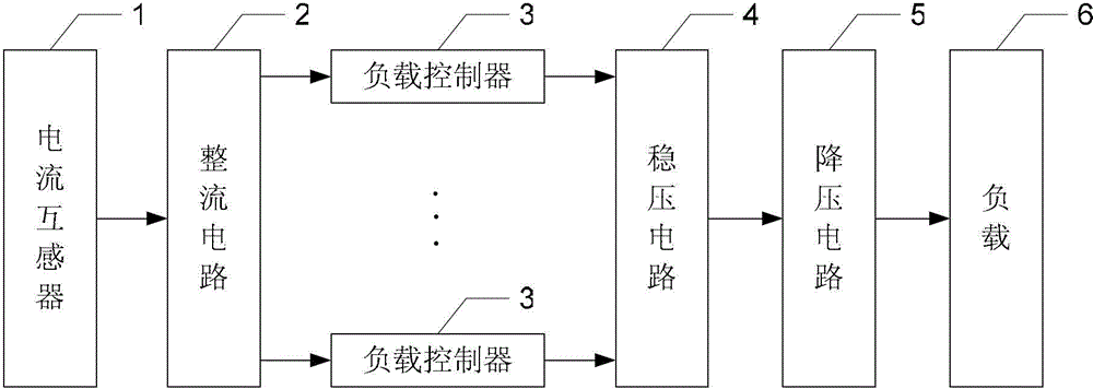
[0029] Specific implementation mode one: the following combination figure 1 Describe this embodiment, the current induction power supply of the power grid monitoring device described in this embodiment, the current transformer 1 obtains the secondary current signal by sensing the current in the grid bus, and the secondary side of the current transformer 1 is connected to the rectifier circuit 2, rectifying The output end of the circuit 2 is connected in parallel with a plurality of load controllers 3, the output end of each load controller 3 is connected to the input end of the voltage stabilizing circuit 4, and the output end of the voltage stabilizing circuit 4 is connected to the input end of the step-down circuit 5, The output terminal of the step-down circuit 5 is connected to a load 6 .
specific Embodiment approach 2
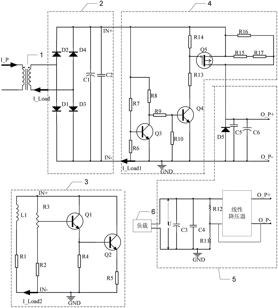
[0030] Specific implementation mode two: the following combination image 3 Describe this embodiment, this embodiment will further explain Embodiment 1. The load controller 3 includes a piezoresistor L1, a resistor R1, a resistor R2, a sliding rheostat R3, a resistor R4, a resistor R5, a first triode Q1 and a second Transistor Q2, the first triode Q1 and the second triode Q2 are all NPN type withstand voltage triodes,
[0031] One end of the varistor L1, one end of the sliding rheostat R3, the collector of the first transistor Q1 and the collector of the second transistor Q2 are simultaneously connected to the positive output terminal IN+ of the rectifier circuit 2,
[0032] One end of the resistor R1, one end of the resistor R2, one end of the resistor R4 and one end of the resistor R5 are simultaneously connected to the negative output terminal IN- of the rectifier circuit 2,
[0033] The other end of the varistor L1 is connected to the other end of the resistor R1,
[003...
specific Embodiment approach 3
[0036] Specific implementation mode three: the following combination image 3 Describe this embodiment, this embodiment will further describe Embodiment 1, the voltage stabilizing circuit 4 includes resistors R6, resistors R7, resistors R8, resistors R9, resistors R10, resistors R13, resistors R14, resistors R15, resistors R16, resistors R17, The third transistor Q3, the fourth transistor Q4, the PMOS transistor Q5, the third transistor Q3 and the fourth transistor Q4 are all NPN transistors,
[0037] One end of the resistor R7, one end of the resistor R8, one end of the resistor R14, one end of the resistor R16, the source of the PMOS transistor Q5, and one end of the resistor R15 are simultaneously connected to the positive output terminal IN+ of the rectifier circuit 2,
[0038] One end of the resistor R6, the emitter of the third transistor Q3, one end of the resistor R10 and the emitter of the fourth transistor Q4 are simultaneously grounded to GND,
[0039] The other en...
PUM
 Abstract
Description
Claims
Application Information
 - R&D
- Intellectual Property
- Life Sciences
- Materials
- Tech Scout
- Unparalleled Data Quality
- Higher Quality Content
- 60% Fewer Hallucinations
Browse by: Latest US Patents, China's latest patents, Technical Efficacy Thesaurus, Application Domain, Technology Topic, Popular Technical Reports.
© 2025 PatSnap. All rights reserved.Legal|Privacy policy|Modern Slavery Act Transparency Statement|Sitemap|About US| Contact US: help@patsnap.com