Node heating method for ground potential treatment substation equipment

A technology of substation equipment and ground potential, applied in substation grounding layout, electrical components, switchgear, etc., can solve problems such as difficulty in effectively eliminating heating defects, inability to open the contact surface for processing, and restriction of processing effect, so as to achieve convenient installation and avoid The effect of direct contact and convenient operation

Active Publication Date: 2012-12-12
STATE GRID CORP OF CHINA +2
View PDF3 Cites 6 Cited by
  • Summary
  • Abstract
  • Description
  • Claims
  • Application Information

AI Technical Summary

Problems solved by technology

At present, the position operation method can only use bolt fasteners for fastening operations. When the heating nodes have contact surface oxidation, bolt corrosion, etc., and the safety distance of equipment is difficult to meet the requirements of equipotential operation, it is difficult to effectively eliminate heating defects.
At the same time, for some equipment that cannot be transferred, even if the potential is equal, the contact surface cannot be opened for treatment, and the treatment effect is also restricted. During special peak periods of electricity consumption such as summer, the equipment often heats up.

Method used


Image

  • Node heating method for ground potential treatment substation equipment
  • Node heating method for ground potential treatment substation equipment
  • Node heating method for ground potential treatment substation equipment

Examples


Embodiment 1

[0059] A ground potential treatment method for heat generation of substation equipment nodes, the steps are as follows:

[0060] (1) The ground potential electrician first installs the rust remover paint spraying device for the ground potential operation and sprays the rust remover on the bolts at the hot spot. (2) Use the bolt removal tool for the ground potential work to disassemble the bolts at the hot spot. (3) The ground potential electrician uses an insulating operating rod to prop up the lead wire end, and then grinds the contact surface with the ground potential work grinding device. The job transports the gasket tool to restore the bolted connection and tighten it.

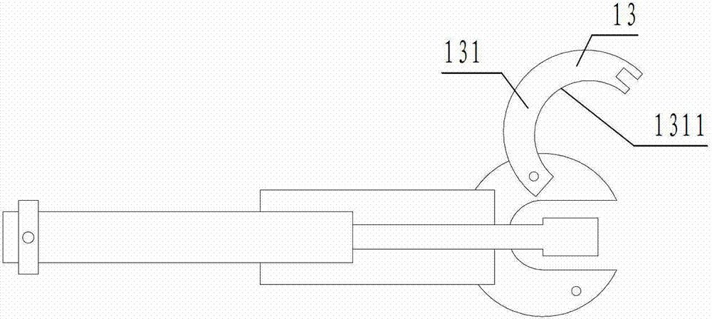
[0061] as described figure 1 , 2 The shown rust remover spraying device for ground potential operation is a clamp-like structure. The clamp-like structure includes two monomers 11 arranged crosswise and hinged together. The two monomers are divided into clamping ends and At the handle end, a pressing p...

Embodiment 2

[0067] This embodiment is basically the same as Embodiment 1, except that when using the ground potential working bolt dismounting tool to disassemble the heat point bolts, one ground potential electrician uses a stop wrench to prevent the bolts from rotating, and the other uses a tool to loosen the bolts, and Disassemble one by one. The ground potential treatment method for heat generation of substation equipment nodes further includes using ground potential work diversion wire clips to shunt the heat generation points.

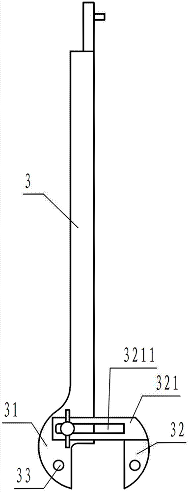
[0068] The specific operation of shunting the heating point is as follows: (1) the ground potential electrician first hangs 2 pulleys and insulating transfer ropes above the heating point, (2) the ground potential electrician assembles the ground potential work diversion wire clip into the required (3) Hang the two ends of the two clamps of the ground potential work diversion wire clamp on the two transmission ropes respectively, and hang two control ropes a...


PUM


Abstract

The invention discloses a node heating method for ground potential treatment substation equipment. The method comprises the following steps that (1) a ground potential operation de-rusting paint spraying device is firstly provided with rust remover by a ground potential electrician, so that bolts at heating points are sprayed; (2) the bolts at the heating points are removed by a ground potential operation bolt removing tool; (3) the ground potential electrician lifts up a lead end by an insulation operation rod, and polishes the contact surface with a ground potential operation polishing device; and (4) after the contact surface is polished, the lead end is put down, and the bolts are connected again and screwed tightly by the bolt removing tool and a ground potential operation conveying cushion tool. The node heating method for the ground potential treatment substation equipment provided by the invention can be used for performing charged processing on the heating point of the no-load equipment capable of transferring a load, and further can install temporary parallel connecting tools at two ends of the heating point with a load, and thus, the operation range is enlarged and the commonality is enhanced.

Description

technical field [0001] The invention relates to a ground potential operation method, in particular to a ground potential treatment method for heat generation of substation equipment nodes. [0002] Background technique [0003] When dealing with heat generation of substation switches and knife switch equipment nodes, the basic live work methods include equipotential and ground potential. When using equipotential work, bolt fastening, replacement, and contact surface grinding can be performed on the no-load heating points And so on, the treatment effect is more thorough. At present, the position operation method can only use bolt fasteners for fastening operations. When there are contact surface oxidation and bolt corrosion at the heating nodes, and the safety distance of equipment cannot meet the requirements of equipotential operation, it is difficult to effectively eliminate heating defects. At the same time, for some equipment that cannot be transferred, ...

Claims


Application Information

Patent Timeline
IPC IPC(8): H02B3/00H02B5/01
Inventor 冯振波陈熹郑孝干吴晓杰蔡金林林啸
Owner STATE GRID CORP OF CHINA
Why Eureka
Try Eureka